27.3.3. Drawing of cables and outputs
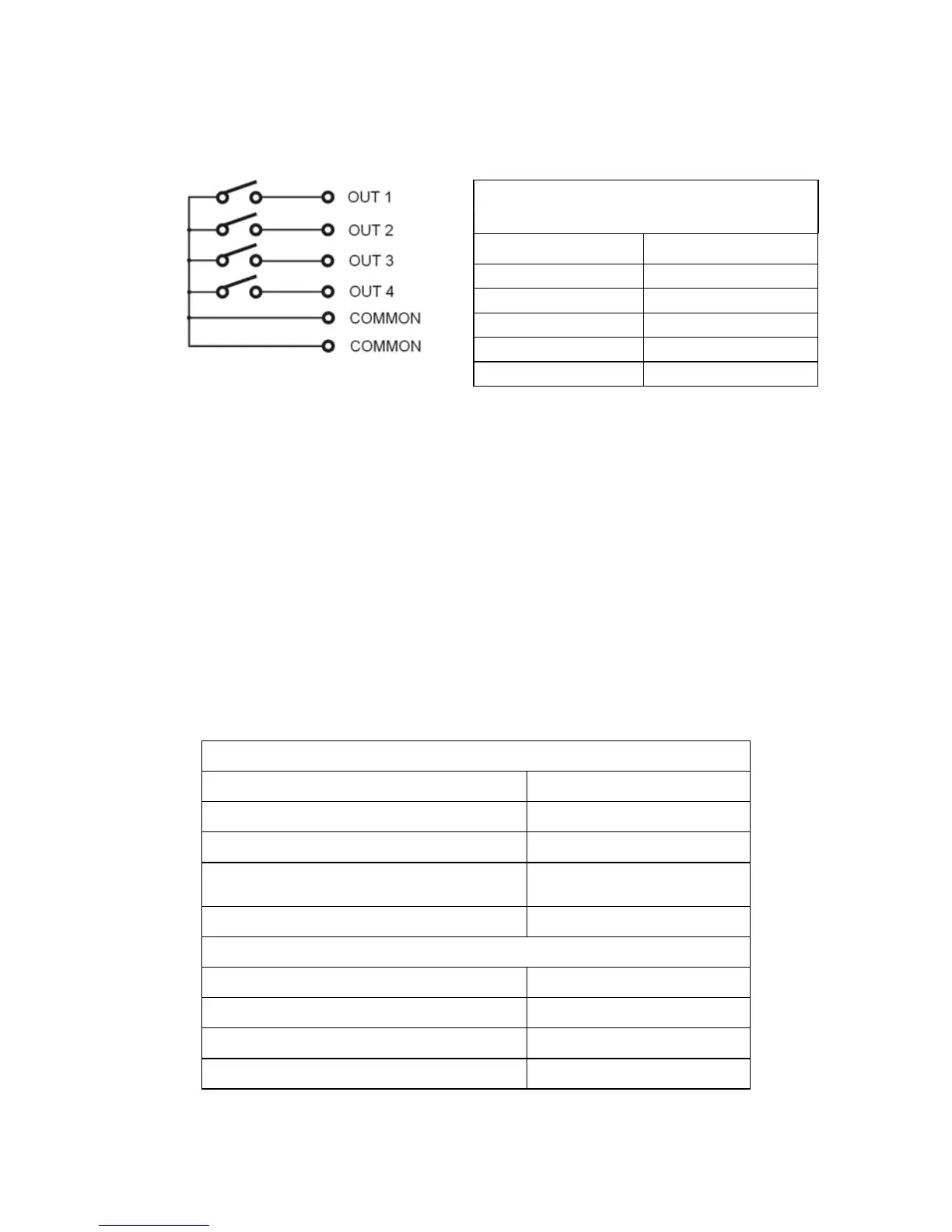
Relay outputs diagram:
SIGNALS AND DESIGNATIONS
OF CONDUCTORS
Wire number Description
1 OUT 1
2 OUT 2
3 OUT 3
4 OUT 4
5 (yellow - green) Common
27.4. WE 4 - 4 inputs / 4 outputs module
WE 4 module comprises 4 optoinsulated inputs and 4 optoinsulated
outputs of reed relays. The input / output wires are led out via a gland
on the back wall of the housing (3m length).
Caution:
As standard indicator is equipped with 3 in and 3 out sockets.
27.4.1. Technical specification
Parameters of outputs
Quantity of outputs 4
Type of outputs Reed operation contacts
Wire diameter 0,14 - 0,5mm
2
Maximal load-current contact
capacity
0,2A DC
Maximal forward voltage 50V DC
Parameters of inputs
Quantity of inputs 4
Input type Optoinsulated
Wire diameter 0,14 – 0,5mm
2
Control voltage range 5 -24V DC
- 142 -