SFC6400A/SFC1450A Synthesized Frequency Upconverter User Interfaces
TM106 – Rev. 1.1 4-1
Section 4 – User Interfaces
4.0 User Interfaces
There are four User Interfaces available for the SFC Upconverter. These are:
Front Panel
Remote Port
Terminal Port
Ethernet Port
4.1 Front Panel User Interface
The Front Panel of the SFC Upconverters allow for complete monitor and control (including but not
limited to operation, calibration, and testing) of all parameters and functions via Monitoring Ports, a
Keypad, LCD Display and Status LEDs.
The front panel layout is shown in Figure 4-1, showing the location and labeling of the front panel.
The front panel is divided into four functional areas: Monitoring Ports, LCD Display, Cursor Control
Arrows, Numeric Keypad, and LED Indicators. Each is described below. Table 4-1 lists each of
these areas. They are further described below.
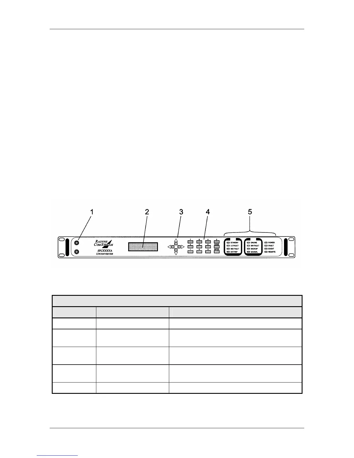
Figure 4-1. SFC Upconverters Front Panel Controls and Indicators
Table 4-1. Front Panel User Interface
Item No. Description Function
1 Monitoring Ports Allow monitoring of the RF and IF Signals.
2 LCD Display Displays SFC Upconverter operating parameters
and configuration data.
3 Cursor Control Arrows Controls the left, right, up, and down motion of the
cursor in the LCD Display window.
4 Numeric Keypad Allows entry of numeric data and Clear and Enter
Function Keys.
5 LED Indicators Displays SFC Upconverter operating status.