Rear Panel Interfaces SFC6400A/SFC1450A Synthesized Frequency Upconverter
5-2 TM106 – Rev. 1.1
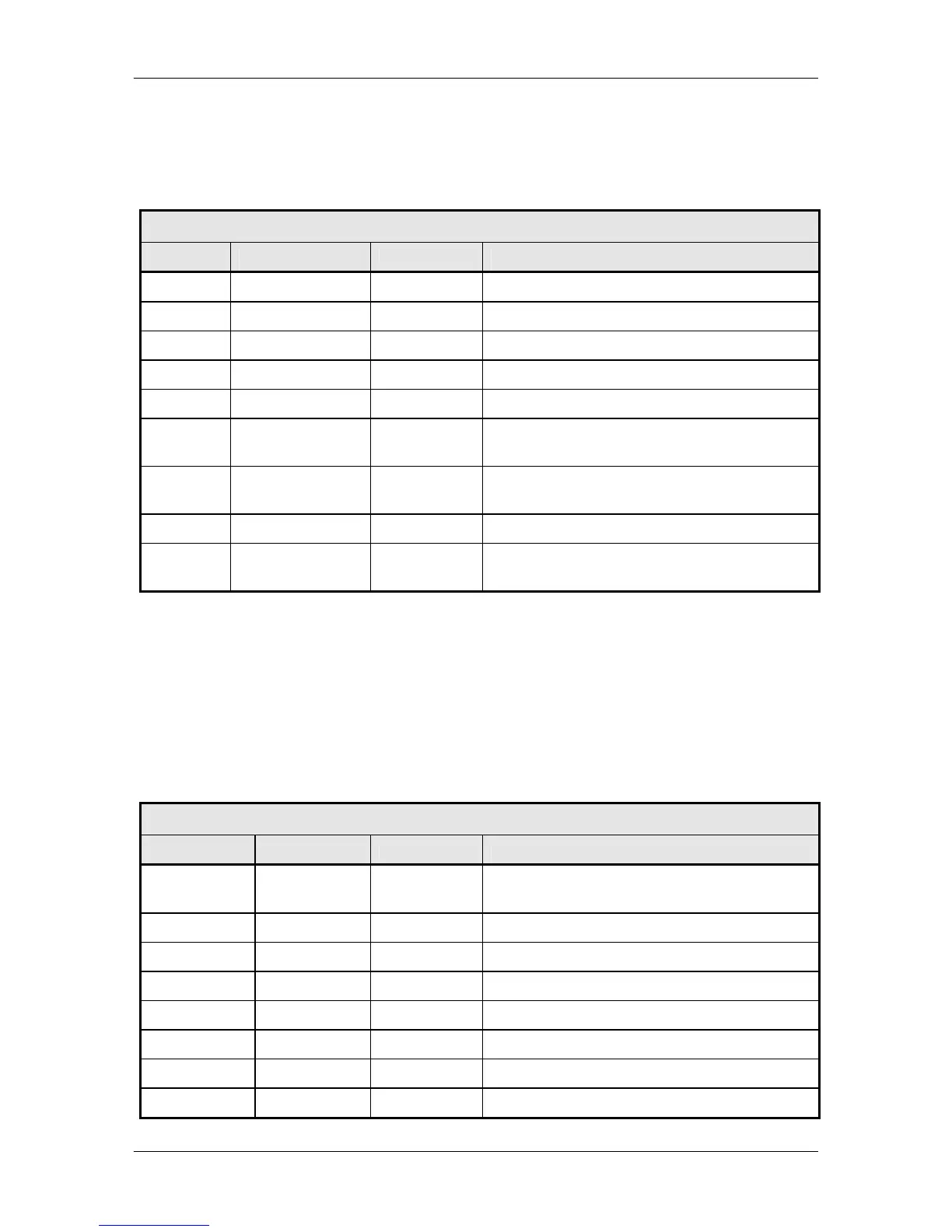
5.4 Test/Fault (J7)
The Test/Fault connector (J7) is a status port that allows monitoring of several system status
indications at the back panel. These items are described in Table 5-1.
Table 5-1. J7 – Test/Fault Interface – D-Sub 9-Pin Female Connector
Pin No. Signal I/O Description
1 N.C. N.A. No Connect
2 IF_LO_FAULT O 1 = LO Fault Condition
3 GND N.A. Ground
4 IF_SIG_DET O Detected Power Level of IF Signal 0 to 5 VDC
5 N.C. N.A. No Connect
6 RLY_NO N.A. Form-C relay normally open contact, summary
fault
7 RLY_NC N.A. Form-C relay normally closed contact,
summary fault
8 RLY_C N.A. Form-C relay common contact, summary fault
9 RF_SIG_DET O Detected Power Level of RF Signal
(Upconverter only, 0 - 5 VDC)
5.5 Operator Serial I/O (J8)
The Operator Serial I/O Port (J8) is a D Sub 9-Pin Female Connector. This port provides a serial
interface that can be configured as either an RS-232 or RS-485 interface and allows the user to
remotely control all of the features outlined in the Serial Protocol (See Section 4.2, Remote Port
User Interfaces). The serial port comes configured as an RS-232 Serial Port for DCE unless
otherwise indicated. The pinout for this interface is listed in Table 5-2. Note that the function of pin
1 and pin 9 depends on whether the protocol is set to RS-232 or RS-485 (Front Panel LCD Menu:
SYSTEM < REMOTE PORT < REMOTE LINE).
Table 5-2. J8 – Operator Serial I/O Port – D-Sub 9-Pin Female Connector
Pin No. Signal I/O Description
1 RX_485 –
RX_232
I Inverted RS-
RS-232 receive
2 TX_485-B O Non-Inverted RS-485 transmit
3 RX_485-B I Non-Inverted RS-485 receive
4 DTR N.A. Connected internally to Pin 6-DSR
5 GND N.A. Ground
6 DSR N.A. Connected internally to Pin 4-DTR
7 RTS N.A. Connected internally to Pin 8-CTS
8 CTS N.A. Connected internally to Pin 7-RTS