Rear Panel Interfaces SFC6400A/SFC1450A Synthesized Frequency Upconverter
5-6 TM106 – Rev. 1.1
Table 5-6. J5 – Backup Switch Interface – D-Sub 15-Pin Female Connector
Pin No. Signal I/O Description
1 RLY_NO N.A. Form-C relay normally open contact, summary
fault
5 RLY_NC N.A. Form-C relay normally closed contact,
summary fault
9 RLY_C N.A. Form-C relay common contact, summary fault
13 GND N.A. Ground
2 +15_OR N.A. Diode Or’d +15 VDC from converter
6 FAULT_INT1 Input RCU101 ONLINE status indicator
10 FAULT_INT2 Input RCU101 Manual Mode indicator A
14 FAULT_INT3 Input RCU101 Manual Mode indicator B
3 FAULT_INT3 N.A. Spare
7 ID_INT0 Input
11 ID_INT1 Input
15 ID_INT2 Input
4 ID_INT3 Input
Converter Switch position ID bits.
8 INT N.A. Spare
12 RMT Output RCU101 Manual Remote Control
5.11 RF In (J1)
The RF In (J1) is the RF Input of the SFC Upconverter. It is an N-Type Female Connector for the
SFC6400A, and an SMA Female Connector for the SFC1450A.
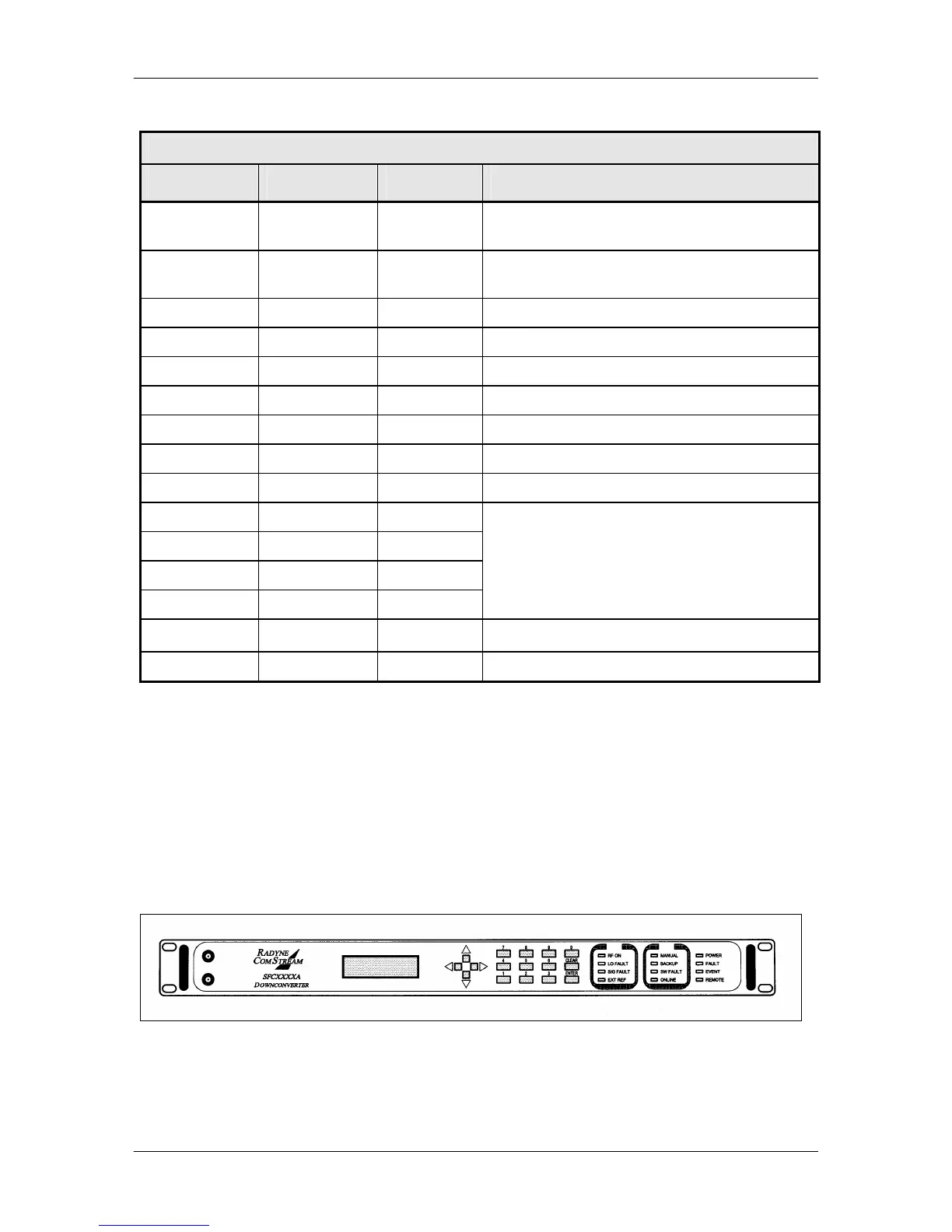
5.12 Monitor Ports
The SFC Upconverters have Monitor Ports located on the Front Panel (Figure 5-7) that allow the
operator to monitor the IF Output and RF Input.
Figure 5-7. SFC Upconverter Front Panel with Monitor Ports