SFC6400A/SFC1450A Synthesized Frequency Upconverter Rear Panel Interfaces
TM106 – Rev. 1.1 5-3
9 TX_485 – A
TX_232
O Inverted RS-
RS-232 Transmit
If the RS-232 option is chosen, an adapter must be used between J8 and the serial cable to the
DTE. One end of the adapter will be a DB9-M connector, which plugs into J8 on the Upconverter
back panel. The other end will be a DB9-F connector, which plugs into the PC serial port or dumb
terminal. The pinout is given in Figure 5-3.
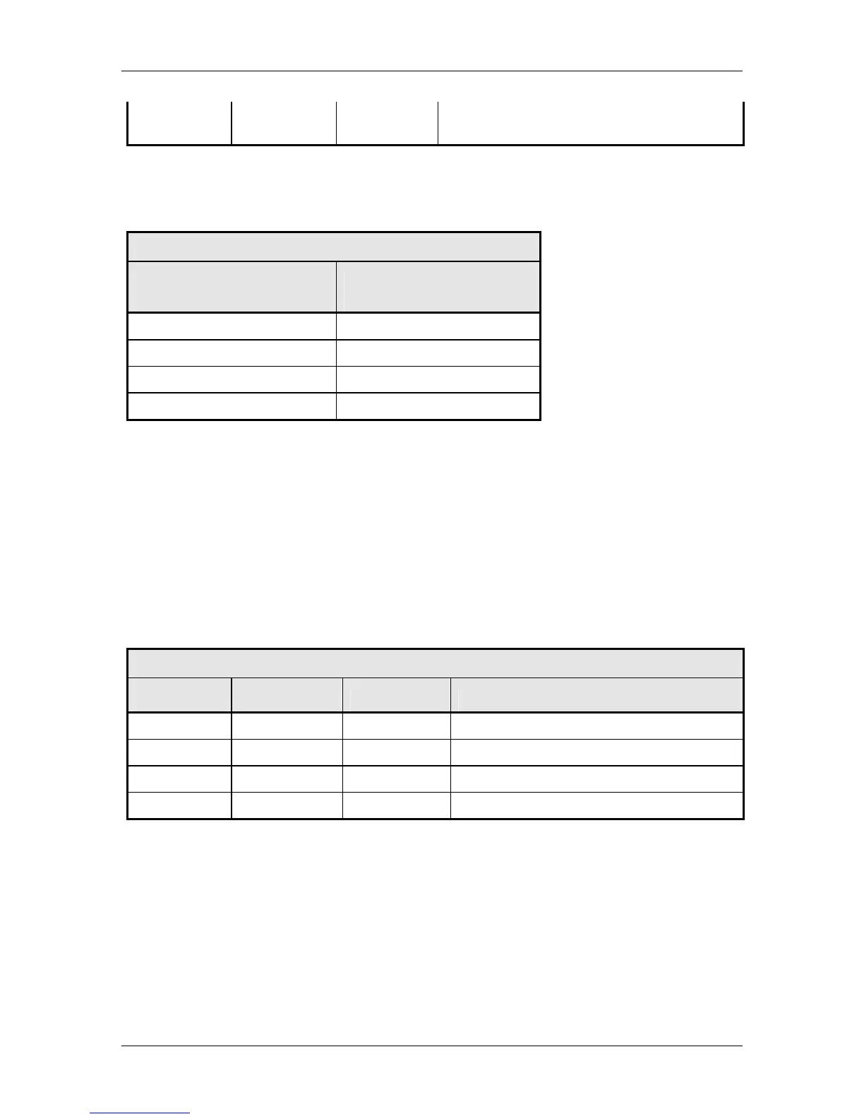
Table 5-3. – RS-232 Adaptor – Operator Serial I/O Port
Pin No. DB9 Male to
Upconverter J8
Pin No. DB9 Female to
DTE
1 3
5 5
9 2
2,3,4,6,7,8 N.A.
5.6 IF Out (J2)
The IF Out Connector (J2) is a 75O BNC-F Connector. Outputs are within 50 – 90 MHz for standard
units and 100 – 180 MHz for units equipped with 140 MHz.
5.7 Terminal (J6)
The Terminal Port allows for complete control and monitoring of all Upconverter parameters and
functions via an RS-232 Serial Interface. The interface comes configured as a DCE device. The
pinout is given in Table 5-4.
Table 5-4. J8 – Terminal Port – D-Sub 9-Pin Female Connector
Pin No. Signal I/O Description
2 TX_232 O RS-232 transmit
3 RX_232 I RS-232 receive
5 GND N.A. Ground
1, 4, 6, 7, 8, 9 N.A. N.A. No Connect
Although the Terminal Port comes configured as a DCE, it can be changed to a DTE by changing
the settings of DIP Switch S3 on the M&C PCB Assembly. Figure 5-2 shows the DIP Switch
settings and resulting configuration.
5.8 Ethernet (J9)
The Ethernet connector can be used for monitor & control functions of the Upconverter. The
physical interface is a standard RJ-45 connector.