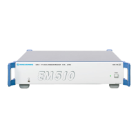
Characteristics EM510
2.7 4065.7763.32-01.00
2.4 Detailed Description
(see Fig. 2-4: EM510 Detailed Block Diagram)
This section deals with the functions of the major functional blocks.
2.4.1 Power Supply Modules
The EM510 operates either on AC or on DC.
- DC voltage: 12 to 32 VDC
- AC voltage: 100 to 240 VAC (115, 230 VAC nominal) with a frequency of 50 to 60 Hz
If both voltage sources are connected, AC supply operation is favored. If the AC supply fails, switch-
over to battery operation is effected automatically.
The mains connector is provided with two mains fuses (F1, F2) and an EMC filter. The mains fuses
protect the electronic circuits against overload and short circuits. The EMC filter prevents radiated
interference from leaving the equipment and also prevents picked-up and conducted interference from
entering the equipment.
The external AC voltage is fed from the mains connector to the AC/DC converter. This converts the AC
voltage into a DC voltage of 24 V, which is fed to the power supply.
The 12 to 32-VDC voltage is fed directly from the DC input to the power supply.
If the POWER switch on the front panel is on, a switch-over circuit in the power supply connects one of
the DC voltages.
The POWER LED indicates whether or not power is being supplied to the power supply.
The power supply contains five DC/DC converters which provide the HF receiver module and the fans
with the required operating voltages. The following stabilized voltages are generated:
For the HF receiver module
+5.15 0.15 VDC / 5.5 A
For the fans
+8 VDC / 0.5 A
All outputs are protected against short circuit and overvoltage. Green LEDs on the power supply
indicate the presence of the DC input and supply voltages.

 Loading...