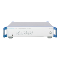
EM510 Characteristics
4065.7763.32-01.00 2.8
2.4.2 HF Receiver Module
The HF receiver module is controlled via the LAN interface X11.
The necessary signal inputs and outputs of the HF receiver module are routed via RF cables to the
connectors on the rear and front panel or are available through the opening in the rear panel.
The RF antenna signal is fed in at connector X1 RF and then taken via RF cable to the RF input of the
HF receiver module. In the digital receiver the received signals are passed through the filters in the
preselection on to the A/D converter, and are subsequently digitally filtered and demodulated to
produce the baseband, video and AF signals. These signals can be transmitted in digital form via the
LAN interface. Together with further output signals for detailed signal analysis and monitoring they are
also made available via the following connectors:
Rear panel:
X6 VIDEO A: Analog video output A for AM and I components
X7 VIDEO B: Analog video output B for FM and Q components
X12a AUDIO: Audio output analog and digital
X14 FPDP: Wideband digital interface. FPDP (Front Panel Data Port) is a platform-independent 32-
bit synchronous data flow path that allows data to be transferred at high speeds (up to 1 Gbit/s),
e.g. AF or baseband signal (I and Q) in digital form.
Front panel:
X10 AF: Phone jack (stereo socket AF_L; AF_R), AF analog headphone output (600 line and
headphones)
For the purposes of synchronization the following inputs and outputs are available on the rear panel:
X8 REF OUT: Output for internal reference signal, f = 10 MHz
X9 REF IN: Input for external reference signal, f = 10 MHz
The HF receiver module can use an internal frequency reference or can be set to synchronize to the
external frequency at X9 REF IN to provide even better frequency accuracy and stability.

 Loading...