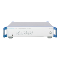
EM510 Preparation for Use
4065.7763.32-01.00 4.2
4.3 Functions of Controls and Indicators
Control and
Indicator
Function
Switch POWER
This switch is used to switch on the EM510.
Green LED
POWER
The LED is illuminated when the mains voltage is applied and the POWER
switch is set to ON.
Yellow LED
100MBIT/S
(rear panel,
Fig. 4-1)
The LED indicates operation in 100 Mbit/s mode.
Green LED
LINK OK
(rear panel,
Fig. 4-1)
The LED will be on if the physical connection to the network is intact.
Yellow LED
RECEIVE
(rear panel,
Fig. 4-1)
The LED will flash yellow if the EM510 receives data from the network. The
frequency of flashing is directly related to the network activity.
Fig. 4-1: LEDs of Ethernet LAN Interface

 Loading...