121
E-02
Select ENABLED and confi rm with ENTER.
Set the coordinate format of the GPS result:
Select COORDINATE FORMAT from the list
using the rotary knob or the cursor keys (∧ or ∨)
and confi rm with ENTER.
Select the desired format and confi rm with
ENTER.
Display the GPS information
When the GPS receiver (HA-Z240, order no.
1309.6700.02) is connected to the R&S FSH AUX
connector on the left side of the instrument, the
position is displayed as a measurement result in a
blue bar in the numeric result area.
When the satellite lock is lost, the bar
turns red and the GPS coordination is in
brackets. The last position, however is still
shown.
The states of satellite lock is indicated in the
titlebar:
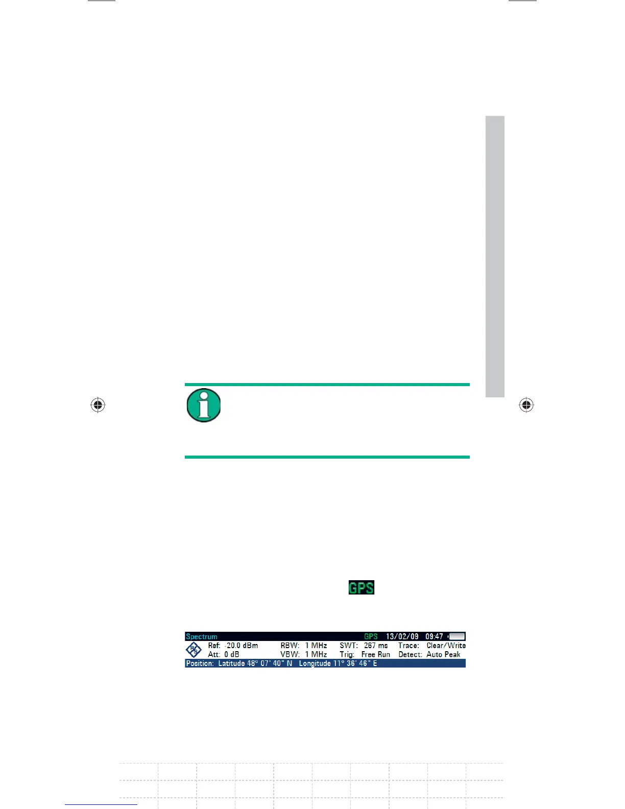
When the GPS receiver function is enabled and
there is a fi x connection with enough satellites
for the GPS mouse to provide the location, in the
titlebar this symbol is shown:
and the GPS
information bar is blue:
GalaxyE_v1-10_3.indd 121GalaxyE_v1-10_3.indd 121 08.04.2009 15:21:5408.04.2009 15:21:54

 Loading...


