40
PD 1309.6269.62-02
Connection for the power sensor
The connection is especially confi gured for power
sensors. It is used for both the power supply and
data transfer via the power sensor interface. The
R&S TS-EMF isotropic antenna (order number
1158.9295.13) can additionally be controlled via this
connection.
Headphone connection
A 3.5 mm jack is provided for headphones. The
internal impedance of the connector is approx.
10 ohm.
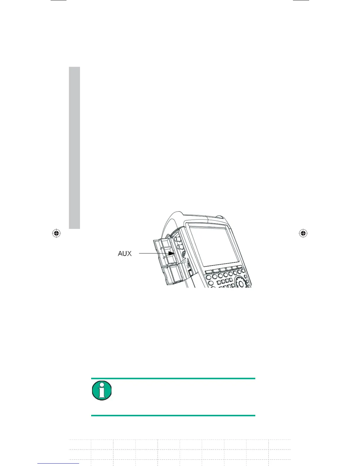
Connection for additional accessories ( AUX)
Further accessories like the GPS receiver (HA-Z240,
order no. 1309.6700.02) can be connected to the
AUX connection on the left side of the instrument.
On the left of the R&S FSH, underneath protective
caps, there are two connections which are
described in more detail below:
Both BNC sockets can be confi gured for
various applications. The names of the
individual connections are embossed on
the insides of the protective covers.
GalaxyE_v1-10_3.indd 40GalaxyE_v1-10_3.indd 40 08.04.2009 15:21:4208.04.2009 15:21:42

 Loading...


