91
E-02
When measuring high powers, pay strict attention
to the following instructions to avoid personal
injury and to prevent the power sensor from being
destroyed:
Danger of skin burns and damage to the
instrument
Never exceed the permissible continuous power.•
See diagram on the rear of the sensor for the •
permissible continuous power.
Turn off the RF power to connect the sensor.•
Screw the RF connectors tightly.•
Operation
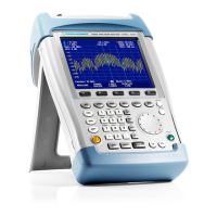
Connect the cable on the power sensor to
the power sensor socket on the R&S FSH and
screw it on. Insert the directional power sensor
between the source and the load.
Press the MODE key.
Press the POWER METER softkey.
The R&S FSH changes to power measurement
mode and opens the screen and the menu for
the directional power measurement. If no power
sensor is connected, no measured value is
displayed. If a power sensor is connected, the
R&S FSH establishes a connection to the power
sensor via the interface and, after a few seconds,
displays the connected power sensor type
(R&S FSH-Z14 or R&S FSH-Z44) as well as the
measured forward power and return loss of the
load.
GalaxyE_v1-10_3.indd 91GalaxyE_v1-10_3.indd 91 08.04.2009 15:21:5008.04.2009 15:21:50

 Loading...