EasyManuals Logo

Raven SmarTrax MD User Manual

Default Icon
136 pages
To Next Page IconTo Next Page
To Previous Page IconTo Previous Page
Page #105 background imageLoading...
Page #105 background image
CHAPTER
6
P/N 016-5030-020 Rev. D 99
CHAPTER 6
TROUBLESHOOTING
NODE
The SmarTrax MD CAN control node features several green light-emitting diodes (LEDs) which may be used to
diagnose issues within the SmarTrax MD system.
NOTE: If the LEDs are not displayed as outlined in the figure below or are all on continuously, check the CAN
connections and the control cable connections on the node. If the issue persists, contact your local
Raven dealer for additional technical support.
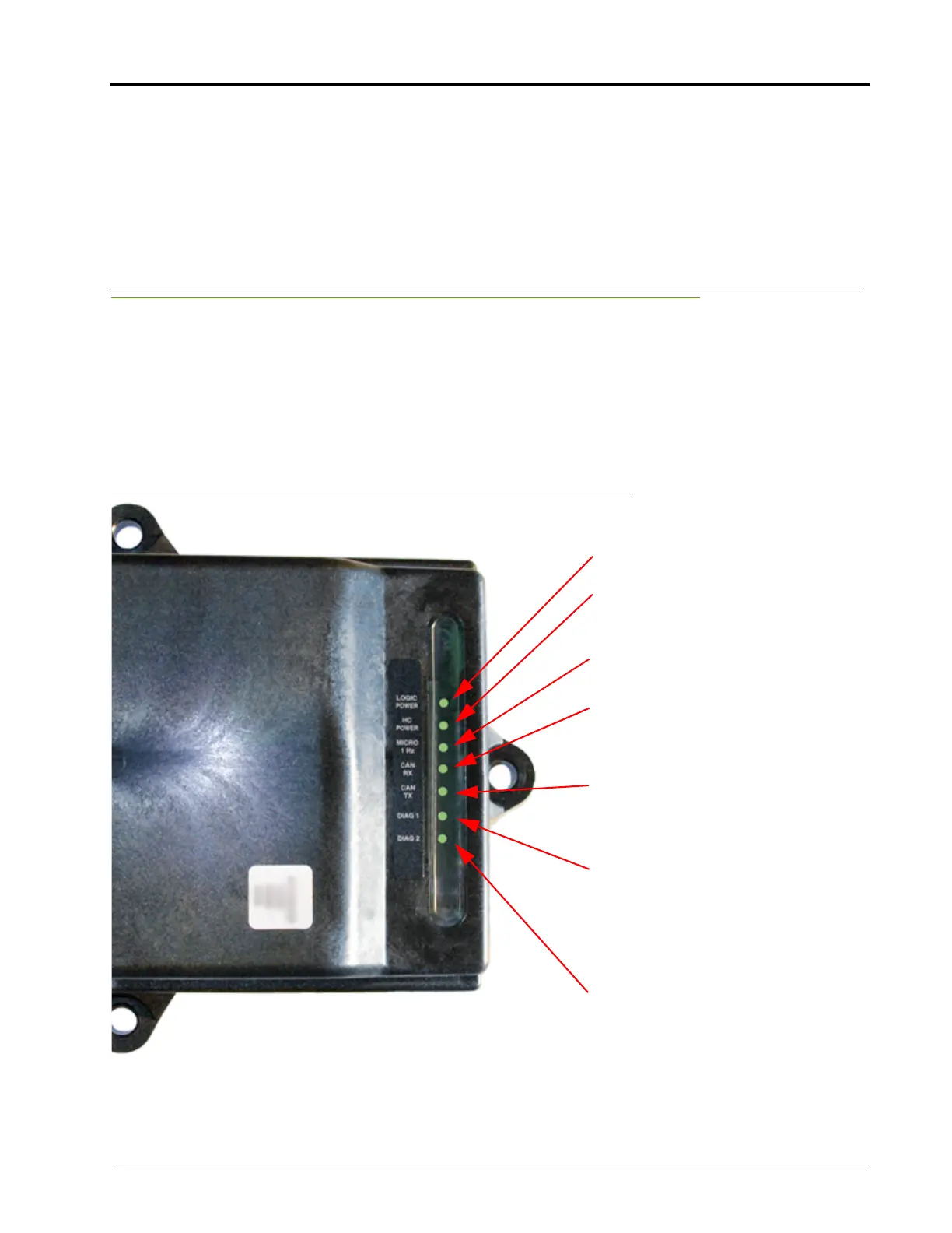
FIGURE 1. SmarTrax MD CAN Control Node LEDs
LOGIC POWER - Lit when +12 V
current is supplied to the node.
HC (High Current) POWER - Lit when
High Current Power is supplied to the
node.
MICRO 1 Hz - Flashes once every
second during processor activity.
CAN RX - Flashes to indicate CAN or
Cruizer II messages are being received
by the node. This light typically flashes
rapidly.
CAN TX - Flashes to indicate CAN or
Cruizer messages are being
transmitted from the node. The flash
speed of this light varies.
DIAG 1 - Indicates the node is
receiving valid GGA messages. This
light must be lit in order to engage
SmarTrax. This light cannot be used to
verify that the field computer is
receiving GPS signals.
DIAG 2 - Lit when the 3D terrain
compensation is activated, but does
not indicate 3D terrain compensation
is actively receiving GPS signal for
correction. To verify 3D terrain
compensation is engaged, access the
3D terrain compensation menu on the
field computer.

Table of Contents

Other manuals for Raven SmarTrax MD

Questions and Answers:

Question and Answer IconNeed help?

Do you have a question about the Raven SmarTrax MD and is the answer not in the manual?

Raven SmarTrax MD Specifications

General IconGeneral
BrandRaven
ModelSmarTrax MD
CategoryAutopilot System
LanguageEnglish