5
P/N 016-5030-020 Rev. D 77
ENVIZIO PRO AND CRUIZER II CONSOLES CALIBRATION AND OPERATION
10. Select Next.
CALIBRATE THE SMARTRAX MD SYSTEM
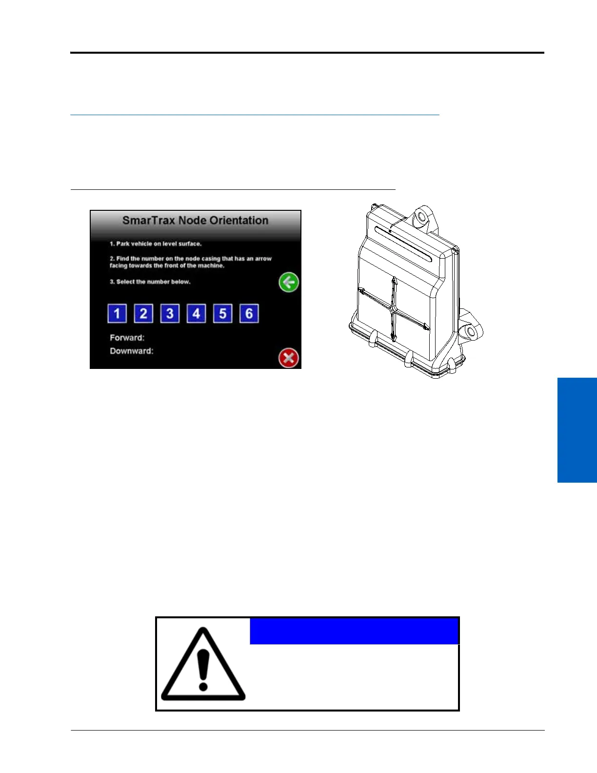
NODE ORIENTATION
FIGURE 8. Node Orientation Screen
1. Park the machine on a level surface.
2. Select the number that corresponds with the node arrow number pointing forward on the machine.
3. Allow the SmarTrax node to calibrate the internal sensors.
NOTE: The SmarTrax MD Setup Wizard will automatically advance to the next step in the calibration process
once the node calibration is complete.
CONFIGURING WHEEL BASE AND ANTENNA OFFSETS
If a generic machine profile was selected during the machine configuration process, the Wheel Base, Antenna
Position, and Antenna Height values must be entered into the SmarTrax MD system.
IMPORTANT: If a specific machine profile was selected during the machine configuration process, the Wheel Base,
Antenna Position, and Antenna Height measurements will be automatically populated in the screen.
However, the antenna mounting position may vary on the machine, so it is important to re-measure the
Antenna Position and Antenna Height to verify that the setting in the field computer is correct. The Wheel
Base value cannot be changed.
NOTICE
The Wheel Base, Antenna Position, and Antenna
Height values are critical to the operation of the
SmarTrax MD system. Measure these dimensions
accurately to ensure optimal SmarTrax MD
system performance!