10
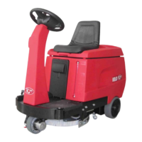
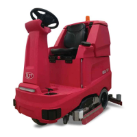
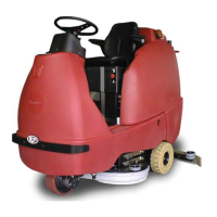
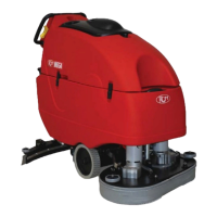
DESCRIPTION OF THE MACHINE
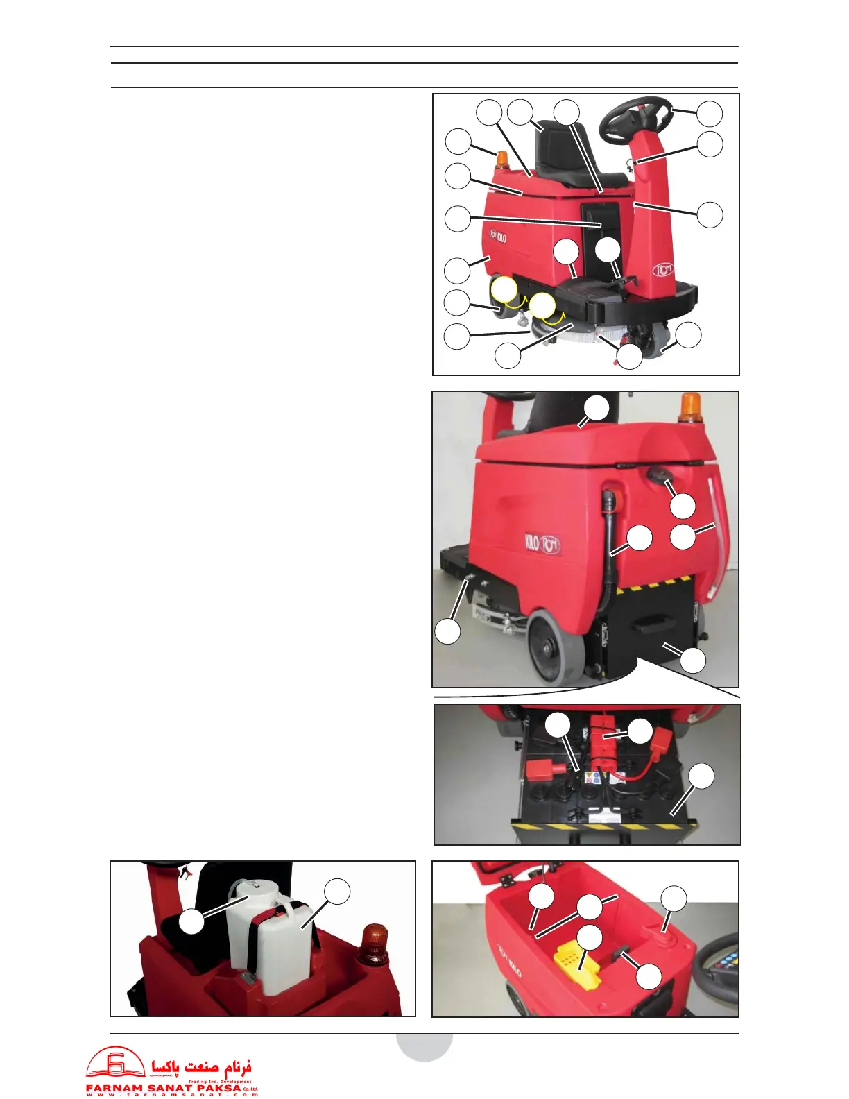
Structure of the machine
1. Steering wheel.
2. Ignition key. “0” o , “I” on.
3. Gear start and acceleration pedal.
4. Detergent solution (or washing water) level indicator.
5. Front, traction and steering wheel with electromagnetic
brake.
6. Rear wheels.
7. Disc brush, or pad holder disc (KILO with disc brushes
base)
8. Batteries connector.
9. Squeegee.
10. Brush(es) base.
11. Detergent solution (or washing water) tank.
12. Recovery water tank.
13. Tanks cover.
14. Tanks cover lifting grip.
15. Operator's seat.
16. Protective panel of electrical-electronic compartment.
17. Detergent solution (or washing water) lter.
18. Heel cushion.
19. Recovery water tank pipe level
20. Detergent tank (DETERSAVER - upon request) (*).
21. Detergent tank cap (DETERSAVER - upon request) (*).
(*) = Automatic “5-litre tank” detergent feeding system (DE-
TERSAVER) parts.
22. Detergent solution (or washing water) tank cap.
23. Recovery water emptying tube.
24. Washing water drain tap.
25. Batteries holder case.
26. Flashing light (upon request).
27. Slot for (recovery water), breakwater protection
wall (antisplash feature).
28. Storage container.
29. Side pins indicating brush(es) height.
30. Connector connecting the machine’s battery
charger to the electrical mains (upon request).
31. Recovery water tank.
32. Recovery water tank oat.
33. Suction inlet (with vacuum motor protection).
34. Recovery water inlet (with debris recovery tray).
35. Batteries.
31
32
33
34
27
35
8
30
1
2
3
5
6
9
7
10
11
12
13 14
15
16
18
17
4
24
26
20
21
22
23
25
28
29
19