R8C/1A Group, R8C/1B Group 12. Interrupts
Rev.1.30 Dec 08, 2006 Page 93 of 315
REJ09B0252-0130
12.2.3 INT1 Interrupt
The INT1 interrupt is generated by an INT1 input. The edge polarity is selected by the R0EDG bit in the TXMR
register.
When the CNTRSEL bit in the UCON register is set to 0, the INT10
pin becomes the INT1 input pin. When the
CNTRSEL bit is set to 1, the INT11
pin becomes the INT1 input pin.
The INT10
pin is shared with the CNTR00 pin and the INT11 pin is shared with the CNTR01 pin.
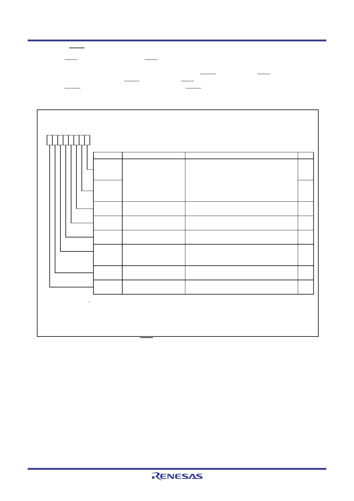
Figure 12.14 shows the TXMR Register when INT1 Interrupt is Used.
Figure 12.14 TXMR Register when INT1
Interrupt is Used
Timer X Mode Register
Symbol Address After Reset
TXMR
008Bh 00h
Bit Symbol Bit Name Function RW
INT1
____
/CNTR0 polarity switch
bit
(2)
P3_7/CNTR0
_______
select bit
NOTES :
1.
2.
3.
R0EDG RW
0 : Rising edge
1 : Falling edge
TXUND RW
RW
TXMOD2
Operating mode select
bit 2
0 : Other than pulse period measurement mode
1 : Pulse period measurement mode
RW
TXMOD0 RW
TXMOD1 RW
b3 b2 b1 b0b7 b6 b5 b4
TXS
Timer X count start flag
(3)
0 : Stops counting.
1 : Starts counting.
The IR bit in the INT1IC register may be set to 1 (requests interrupt) w hen the R0EDG bit is rew ritten. Refer to
12.5.5
Changing Interrupt Sources.
When using INT1
____
interrupt, select modes other than pulse output mode.
TXEDG RW
Ref er to
14.1.6 Notes on Timer X
for precautions regarding the TXS bit.
Timer X underflow flag Function varies depending on operating mode.
Operating mode select bits
0, 1
(1)
b1 b0
0 0 : Timer mode or pulse period measurement
mode
0 1 : Do not set.
1 0 : Event count mode
1 1 : Pulse w idth measurement mode
RW
TXOCNT
Function varies depending on operating mode.
Function varies depending on operating mode.Active edge reception flag
 Loading...


