R8C/1A Group, R8C/1B Group 10. Clock Generation Circuit
Rev.1.30 Dec 08, 2006 Page 72 of 315
REJ09B0252-0130
10.4.3 Stop Mode
Since the oscillator circuits stop in stop mode, the CPU clock and peripheral function clock stop and the CPU
and peripheral functions that use these clocks stop operating. The least power required to operate the MCU is in
stop mode. If the voltage applied to the VCC pin is VRAM or more, the contents of internal RAM is
maintained.
The peripheral functions clocked by external signals continue operating. Table 10.4 lists Interrupts to Exit Stop
Mode and Usage Conditions.
10.4.3.1 Entering Stop Mode
The MCU enters stop mode when the CM10 bit in the CM1 register is set to 1 (all clocks stop). At the same
time, the CM06 bit in the CM0 register is set to 1 (divide-by-8 mode) and the CM15 bit in the CM10 register is
set to 1 (main clock oscillator circuit drive capability high).
When using stop mode, set bits OCD1 to OCD0 to 00b (oscillation stop detection function disabled) before
entering stop mode.
10.4.3.2 Pin Status in Stop Mode
The status before wait mode was entered is maintained.
However, when the CM13 bit in the CM1 register is set to 1 (XIN-XOUT pins), the XOUT(P4_7) pin is held
“H”. When the CM13 bit is set to 0 (input ports P4_6 and P4_7), the P4_7(XOUT) pin is held in input status.
10.4.3.3 Exiting Stop Mode
The MCU exits stop mode by a hardware reset or peripheral function interrupt.
Figure 10.9 shows the Time from Stop Mode to Interrupt Routine Execution.
When using a hardware reset to exit stop mode, set bits ILVL2 to ILVL0 for the peripheral function interrupts
to 000b (interrupts disabled) before setting the CM10 bit to 1.
When using a peripheral function interrupt to exit stop mode, set up the following before setting the CM10 bit
to 1.
(1) Set the interrupt priority level in bits ILVL2 to ILVL0 of the peripheral function interrupts to be used
for exiting stop mode. Set bits ILVL2 to ILVL0 of the peripheral function interrupts that are not to be
used for exiting stop mode to 000b (interrupt disabled).
(2) Set the I flag to 1.
(3) Operate the peripheral function to be used for exiting stop mode.
When exiting by a peripheral function interrupt, the interrupt sequence is executed when an interrupt
request is generated and the CPU clock supply is started.
The CPU clock, when exiting stop mode by a peripheral function interrupt, is the divide-by-8 of the clock
which was used before stop mode was entered.
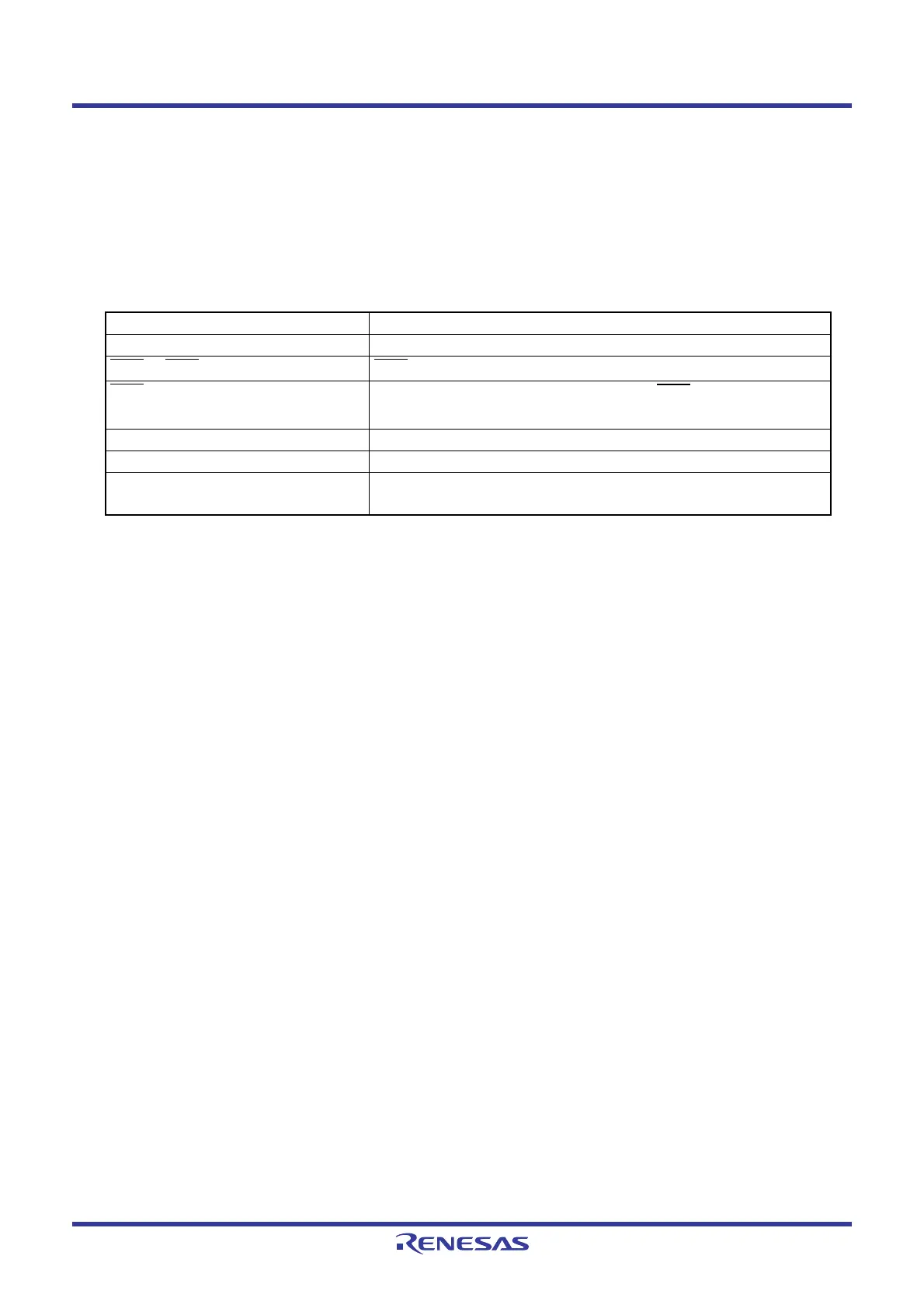
Table 10.4 Interrupts to Exit Stop Mode and Usage Conditions
Interrupt Usage Conditions
Key input interrupt −
INT0
to INT1 interrupts INT0 can be used if there is no filter.
INT3
interrupt
No filter. Interrupt request is generated at INT3
input (TCC06 bit in
TCC0 register is set to 1).
Timer X interrupt When external pulse is counted in event counter mode.
Serial interface interrupt When external clock is selected.
Voltage monitor 2 interrupt Usable in digital filter disabled mode (VW2C1 bit in VW2C register
is set to 1)
 Loading...


