R8C/1A Group, R8C/1B Group 16. Clock Synchronous Serial Interface
Rev.1.30 Dec 08, 2006 Page 184 of 315
REJ09B0252-0130
16.2.5 Clock Synchronous Communication Mode
16.2.5.1 Initialization in Clock Synchronous Communication Mode
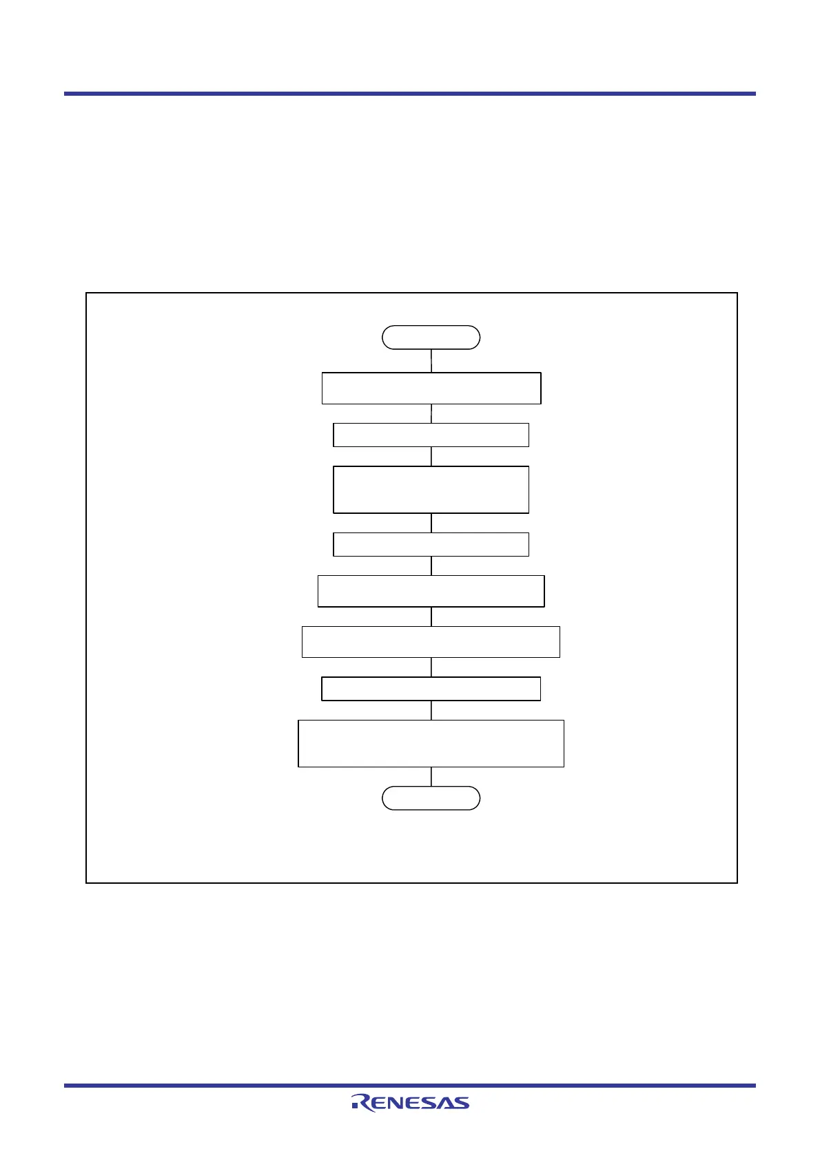
Figure 16.12 shows Initialization in Clock Synchronous Communication Mode. To initialize, set the TE bit in
the SSER register to 0 (transmit disabled) and the RE bit to 0 (receive disabled) before data transmission or
reception.
Set the TE bit to 0 and the RE bit to 0 before changing the communication mode or format.
Setting the RE bit to 0 does not change the contents of flags RDRF and ORER and the contents of the SSRDR
register.
Figure 16.12 Initialization in Clock Synchronous Communication Mode
Start
SSMR2 register SSUMS bit ← 0
SSCRH register Set bits CKS0 to CKS2
Set RSSTP bit
SSSR register ORER bit ← 0
(1)
SSER register RE bit ← 1 (receive)
TE bit
← 1 (transmit)
Set bits RIE, TEIE, and TIE
End
NOTE:
1. Write 0 after reading 1 to set the ORER bit to 0.
SSER register RE bit ← 0
TE bit
← 0
SSMR2 register SCKS bit ← 1
Set SOOS bit
SSCRH register Set MSS bit
SSMR register CPHS bit ← 0
CPOS bit
← 0
Set MLS bit
 Loading...


