R8C/1A Group, R8C/1B Group 14. Timers
Rev.1.30 Dec 08, 2006 Page 109 of 315
REJ09B0252-0130
14.1 Timer X
Timer X is an 8-bit timer with an 8-bit prescaler.
The prescaler and timer each consist of a reload register and counter. The reload register and counter are allocated
at the same address, and can be accessed when accessing registers PREX and TX (refer to Tables 14.2 to 14.6 the
Specifications of Each Mode).
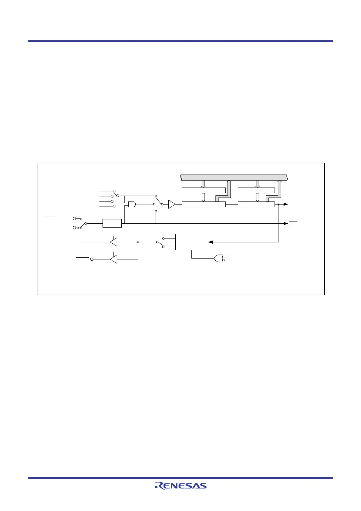
Figure 14.1 shows a Block Diagram of Timer X. Figures 14.2 and 14.3 show the registers associated with Timer X.
Timer X has the following five operating modes:
• Timer mode: The timer counts the internal count source.
• Pulse output mode: The timer counts the internal count source and outputs pulses which
inverts the polarity by underflow of the timer.
• Event counter mode: The timer counts external pulses.
• Pulse width measurement mode: The timer measures the pulse width of an external pulse.
• Pulse period measurement mode: The timer measures the pulse period of an external pulse.
Figure 14.1 Block Diagram of Timer X
= 00b
= 01b
= 11b
f2
f8
f1
= 10b
fRING
TXCK1 to TXCK0
TXMOD1 to TXMOD0
= 00b or 01b
= 11b
= 10b
TXS bit
Counter
Reload register
PREX register
Counter
Reload register
TX register
Data Bus
Timer X interrupt
INT1 interrupt
Write to TX register
Bits TXMOD1 to TXMOD0 = 01b
TXMOD0 to TXMOD1, R0EDG, TXS, TXOCNT: Bits in TXMR register
TXCK0 to TXCK1: Bits in TCSS register
CNTRSEL: Bit in UCON register
Toggle flip-flop
Q
Q
CLR
CK
R0EDG = 1
R0EDG = 0
Polarity
switching
TXMOD1 to TXMOD0
bits = 01b
TXOCNT bit
INT11/CNTR01
CNTR0
INT10/CNTR00
CNTRSEL = 1
CNTRSEL = 0
 Loading...


