R8C/1A Group, R8C/1B Group 10. Clock Generation Circuit
Rev.1.30 Dec 08, 2006 Page 58 of 315
REJ09B0252-0130
10. Clock Generation Circuit
The clock generation circuit has:
• Main clock oscillation circuit
• On-chip oscillator (oscillation stop detection function)
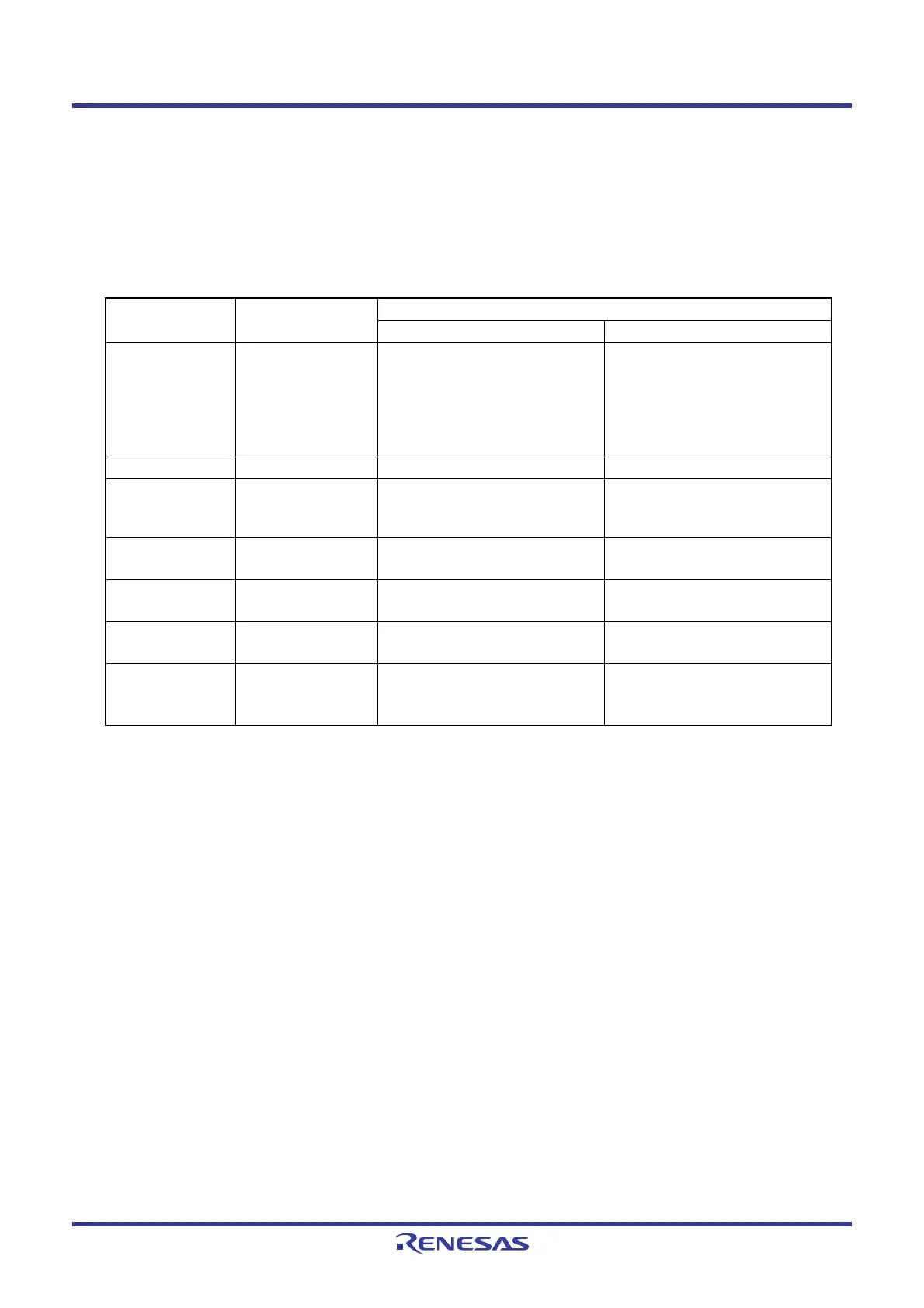
Table 10.1 lists Specifications of Clock Generation Circuit. Figure 10.1 shows a Clock Generation Circuit. Figures 9.2
to 10.5 show clock associated registers.
NOTE:
1. These pins can be used as P4_6 or P4_7 when using the on-chip oscillator clock as the CPU clock
while the main clock oscillation circuit is not used.
Table 10.1 Specifications of Clock Generation Circuit
Item
Main Clock
Oscillation Circuit
On-Chip Oscillator
High-Speed On-Chip Oscillator Low-Speed On-Chip Oscillator
Applications • CPU clock source
• Peripheral
function clock
source
• CPU clock source
• Peripheral function clock
source
• CPU and peripheral function
clock sources when main
clock stops oscillating
• CPU clock source
• Peripheral function clock
source
• CPU and peripheral function
clock sources when main
clock stops oscillating
Clock frequency 0 to 20 MHz Approx. 8 MHz Approx. 125 kHz
Connectable
oscillator
•Ceramic
resonator
• Crystal oscillator
−−
Oscillator
connect pins
XIN, XOUT
(1)
(Note 1) (Note 1)
Oscillation stop,
restart function
Usable Usable Usable
Oscillator status
after reset
Stop Stop Oscillate
Others Externally
generated clock
can be input
−−
 Loading...


