R8C/1A Group, R8C/1B Group 14. Timers
Rev.1.30 Dec 08, 2006 Page 119 of 315
REJ09B0252-0130
14.1.5 Pulse Period Measurement Mode
In pulse period measurement mode, the pulse period of an external signal input to the INT1/CNTR0 pin is
measured (refer to Table 14.6 Pulse Period Measurement Mode Specifications). Figure 14.9 shows the
TXMR Register in Pulse Period Measurement Mode. Figure 14.10 shows an Operating Example in Pulse
Period Measurement Mode.
NOTE:
1. Input a pulse with a period longer than twice of the prescaler X period. Input a pulse with a longer
“H” and “L” width than the prescaler X period. If a pulse with a shorter period is input to the CNTR0
pin, the input may be ignored.
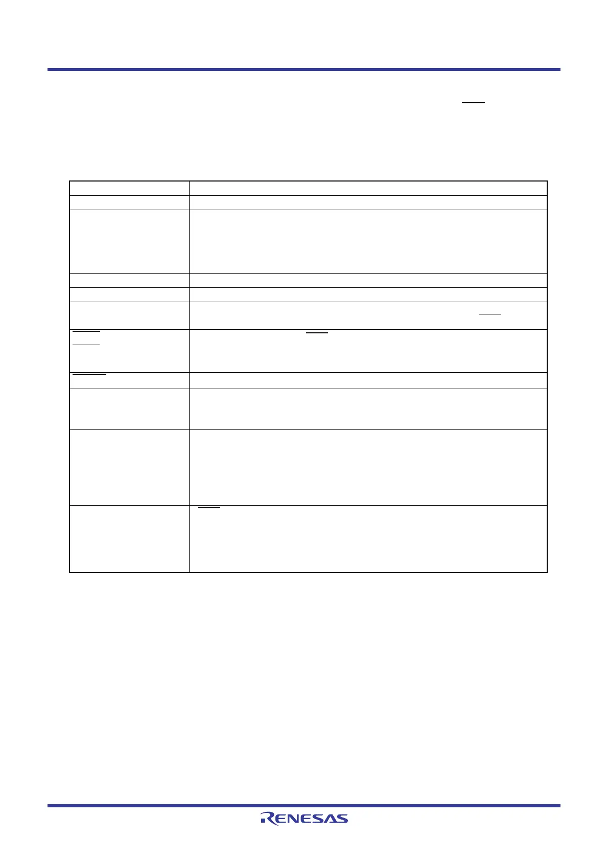
Table 14.6 Pulse Period Measurement Mode Specifications
Item Specification
Count sources f1, f2, f8, fRING
Count operations • Decrement
• After an active edge of the measured pulse is input, contents for the read-out
buffer are retained at the first underflow of prescaler X. Then timer X reloads
contents in the reload register at the second underflow of prescaler X and
continues counting.
Count start condition 1 (count starts) is written to the TXS bit in the TXMR register.
Count stop condition 0 (count stops) is written to the TXS bit in the TXMR register.
Interrupt request
generation timing
• When timer X underflows or reloads [timer X interrupt].
• Rising or falling of CNTR0 input (end of measurement period) [INT1
interrupt]
INT10
/CNTR00,
INT11
/CNTR01
pin functions
Measured pulse input
(1)
(INT1 interrupt input)
CNTR0
pin function
Programmable I/O port
Read from timer Contents of the read-out buffer can be read out by reading the TX register.
The value retained in the read-out buffer is released by reading the TX
register.
Write to timer • When registers TX and PREX are written while the count is stopped, values
are written to both the reload register and counter.
• When registers TX and PREX are written during the count, the value is
written to each reload register of registers TX and PREX at the following
count source input, the data is transferred to the counter at the second count
source input, and the count re-starts at the third count source input.
Select functions
•INT1
/CNTR0 polarity switch function
The R0EDG bit can select the measurement period for the input pulse.
• Measured pulse input pin select function
The CNTRSEL bit in the UCON register can select the CNTR00 or CNTR01
pin.
 Loading...


