R8C/1A Group, R8C/1B Group 12. Interrupts
Rev.1.30 Dec 08, 2006 Page 81 of 315
REJ09B0252-0130
12.1.5 Interrupts and Interrupt Vectors
There are 4 bytes in each vector. Set the starting address of an interrupt routine in each interrupt vector. When
an interrupt request is acknowledged, the CPU branches to the address set in the corresponding interrupt vector.
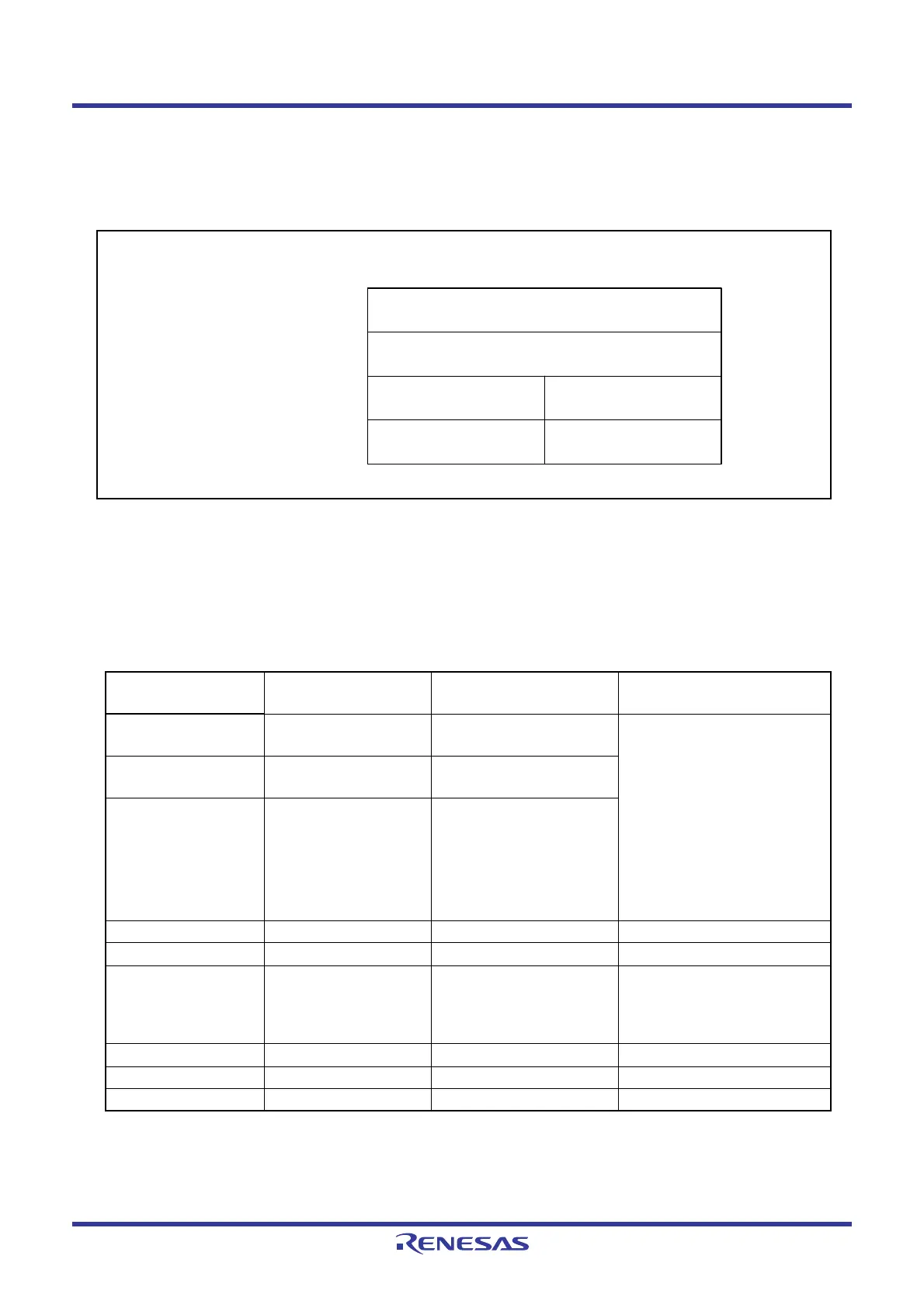
Figure 12.2 shows an Interrupt Vector.
Figure 12.2 Interrupt Vector
12.1.5.1 Fixed Vector Tables
The fixed vector tables are allocated addresses 0FFDCh to 0FFFFh. Table 12.1 lists the Fixed Vector Tables.
The vector addresses (H) of fixed vectors are used by the ID code check function. For details, refer to 18.3
Functions to Prevent Rewriting of Flash Memory.
NOTE:
1. Do not use these interrupts. They are for use by development support tools only.
Table 12.1 Fixed Vector Tables
Interrupt Source
Vector Addresses
Address (L) to (H)
Remarks Reference
Undefined instruction 0FFDCh to 0FFDFh Interrupt on UND
instruction
R8C/Tiny Series Software
Manual
Overflow 0FFE0h to 0FFE3h Interrupt on INTO
instruction
BRK instruction 0FFE4h to 0FFE7h If the content of address
0FFE7h is FFh, program
execution starts from the
address shown by the
vector in the relocatable
vector table.
Address match 0FFE8h to 0FFEBh 12.4 Address Match Interrupt
Single step
(1)
0FFECh to 0FFEFh
• Watchdog timer
• Oscillation stop
detection
• Voltage monitor 2
0FFF0h to 0FFF3h • 13. Watchdog Timer
• 10. Clock Generation Circuit
• 7. Voltage Detection Circuit
Address break
(1)
0FFF4h to 0FFF7h
(Reserved) 0FFF8h to 0FFFBh
Reset 0FFFCh to 0FFFFh 6. Resets
Vector address (L)
Vector address (H)
MSB LSB
Low address
Mid address
High address0 0 0 0
0 0 0 0 0 0 0 0
 Loading...


