R8C/1A Group, R8C/1B Group 12. Interrupts
Rev.1.30 Dec 08, 2006 Page 83 of 315
REJ09B0252-0130
12.1.6 Interrupt Control
The following describes enabling and disabling the maskable interrupts and setting the priority for
acknowledgement. The explanation does not apply to nonmaskable interrupts.
Use the I flag in the FLG register, IPL, and bits ILVL2 to ILVL0 in each interrupt control register to enable or
disable maskable interrupts. Whether an interrupt is requested is indicated by the IR bit in each interrupt control
register.
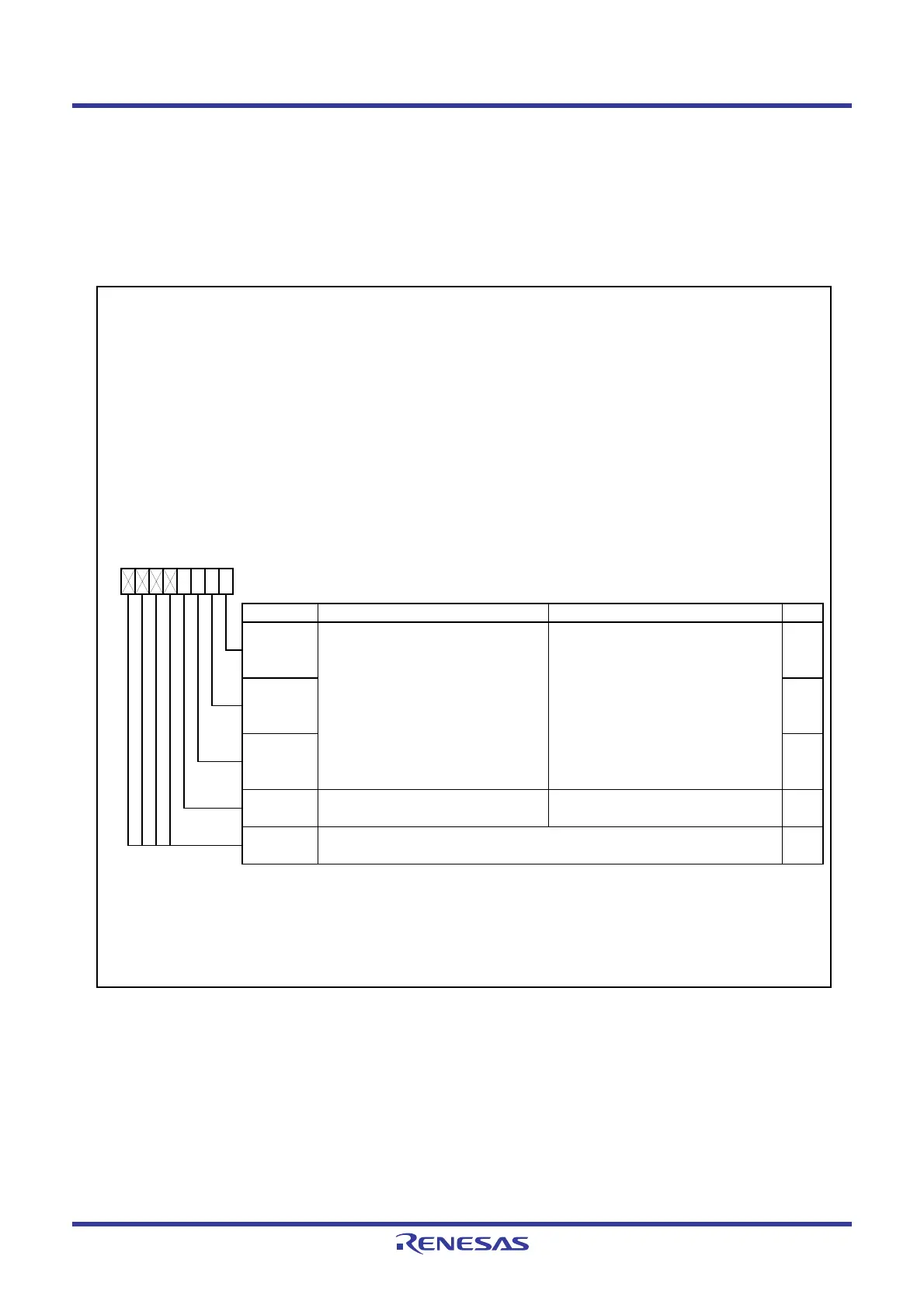
Figure 12.3 shows the Interrupt Control Register and Figure 12.4 shows the INT0IC Register
Figure 12.3 Interrupt Control Register
Interrupt Control Register
(2)
Address After Reset
KUPIC
004Dh XXXXX000b
ADIC
004Eh XXXXX000b
SSUA IC/IIC2A IC
(3)
004Fh XXXXX000b
CMP1IC
0050h XXXXX000b
S0TIC, S1TIC
0051h, 0053h XXXXX000b
S0RIC, S1RIC
0052h, 0054h XXXXX000b
TXIC
0056h XXXXX000b
TZIC
0058h XXXXX000b
INT1IC
0059h XXXXX000b
INT3IC
005Ah XXXXX000b
TCIC
005Bh XXXXX000b
CMP0IC
005Ch XXXXX000b
Bit Symbol Function RW
NOTES :
1.
2.
3.
Symbol
Only 0 can be w ritten to the IR bit. Do not w rite 1.
The IICSEL bit in the PMR register sw itches functions.
IR
0 : Requests no interrupt
1 : Requests interrupt
RW
(1)
—
(b7-b4)
—
Rew rite the interrupt control register w hen the interrupt request w hich is applicable for the register is not generated.
Ref er to
12.5.6 Changing Interrupt Control Registers.
Nothing is assigned. If necessary, set to 0.
When read, the content is undefined.
ILV L0 RW
b2 b1 b0
0 0 0 : Level 0 (interrupt disable)
0 0 1 : Level 1
0 1 0 : Level 2
0 1 1 : Level 3
1 0 0 : Level 4
1 0 1 : Level 5
1 1 0 : Level 6
1 1 1 : Level 7
ILV L1 RW
ILV L2 RW
b7 b6 b5 b4 b3 b2 b1 b0
Bit Name
Interrupt priority level select bits
Interrupt request bit
 Loading...


