R8C/1A Group, R8C/1B GroupAppendix 2. Connection Examples between Serial Writer and On-Chip Debugging
Rev.1.30 Dec 08, 2006 Page 312 of 315
REJ09B0252-0130
Appendix 2. Connection Examples between Serial Writer and On-Chip
Debugging Emulator
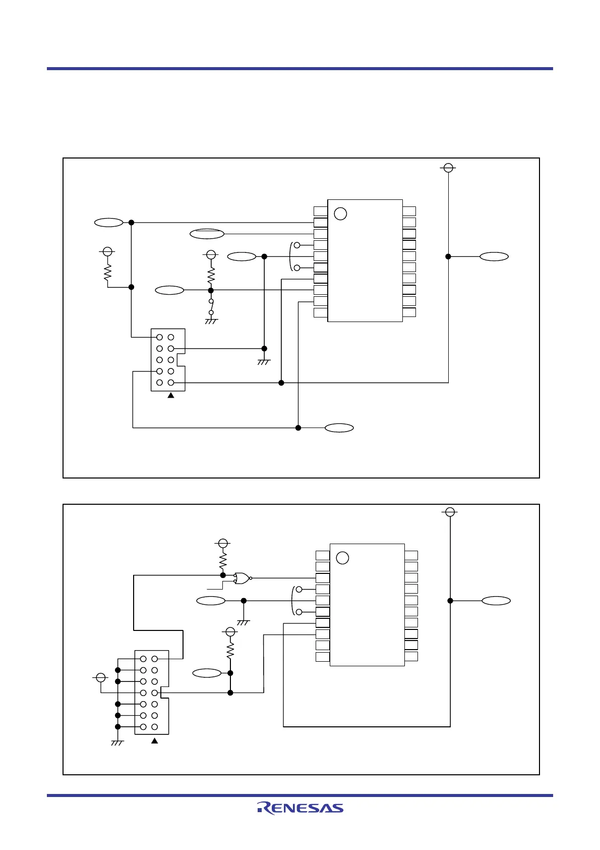
Appendix Figure 2.1 shows a Connection Example with M16C Flash Starter (M3A-0806) and Appendix Figure 2.2
shows a Connection Example with E8 Emulator (R0E000080KCE00).
Appendix Figure 2.1 Connection Example with M16C Flash Starter (M3A-0806)
Appendix Figure 2.2 Connection Example with E8 Emulator (R0E000080KCE00)
VSS VCC
RXD 4
7 VSS
1 VCC
10
M16C flash starter
(M3A-0806)
1
2
3
4
5
6
7
8
9
10
20
19
18
17
16
15
14
13
12
11
R8C/1A, R8C/1B
Group
RXD
TXD
TXD
RESET
MODE
NOTES:
1. An oscillation circuit must be connected, even when
operating with the on-chip oscillator clock.
2. Connect an external reset circuit.
Connect oscillation
circuit
(1)
(2)
VSS VCC
MODE
4.7 kΩ
1
2
3
4
5
6
7
8
9
10
20
19
18
17
16
15
14
13
12
11
R8C/1A, R8C/1B
Group
E8 emulator
(R0E000080KCE00)
RESET
12
10
8
6
4
2
VSS
13
7 MODE
VCC
14
NOTE:
1. It is not necessary to connect an oscillation circuit
when operating with the on-chip oscillator clock.
User reset signal
Connect oscillation
circuit
(1)
 Loading...


