R8C/1A Group, R8C/1B Group 12. Interrupts
Rev.1.30 Dec 08, 2006 Page 94 of 315
REJ09B0252-0130
12.2.4 INT3 Interrupt
The INT3 interrupt is generated by an INT3 input. Set the TCC07 bit in the TCC0 register to 0 (INT3).
When the TCC06 bit in the TCC0 register is set to 0, an INT3
interrupt request is generated in synchronization
with the count source of timer C. If the TCC06 bit is set to 1, the INT3
interrupt request is generated when an
INT3
input occurs.
The INT3
input contains a digital filter. The INT3 level is sampled every sampling clock cycle and if the
sampled input level matches three times, the IR bit in the INT3IC register is set to 1 (interrupt requested). The
sampling clock is selected by bits TCC11 to TCC10 in the TCC1 register. If filter is selected, the interrupt
request is generated in synchronization with the sampling clock, even if the TCC06 bit is set to 1. The P3_3 bit
in the P3 register indicates the value before filtering regardless of the contents set in bits TCC11 to TCC10.
The INT3
pin is used with the TCIN pin.
If the TCC07 bit is set to 1 (fRING128), the INT3
interrupt is generated by the fRING128 clock. The IR bit in
the INT3IC register is set to 1 (interrupt requested) every fRING128 clock cycle or every half fRING128 clock
cycle.
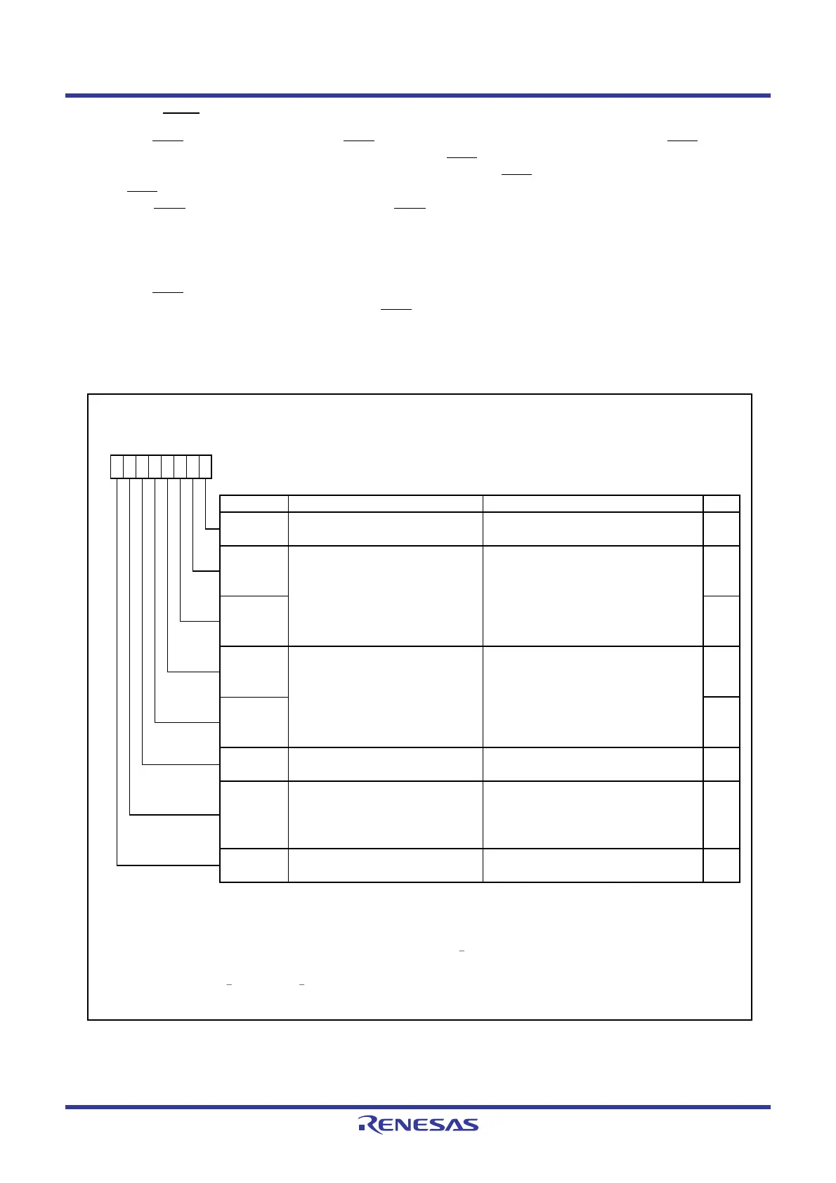
Figure 12.15 shows the TCC0 Register and Figure 12.16 shows the TCC1 Register.
Figure 12.15 TCC0 Register
Timer C Control Register 0
Symbol Address After Reset
TCC0
009Ah 00h
Bit Symbol Bit Name Function RW
INT3
_____
interrupt and capture
polarity select bits
(1,2)
Set to 0.
INT3
____
interrupt request generation 0 : INT3
____
interrupt is generated
timing select bit
(2,3)
in synchronization w ith timer C count.
1 : INT3
____
interrupt is generated w hen
INT3
____
interrupt is input.
(4)
INT3
____
interrupt and capture input 0 : INT3
____
switch bit
(1,2)
1 : fRING128
NOTES :
1.
2.
3.
4.
When the TCC13 bit is set to 1 (output compare mode) and an INT3
____
interrupt is input, regardless of the
When using the INT3
____
filter, the INT3
____
interrupt is generated in synchronization w ith the clock for the digital filter.
setting value of the TCC06 bit, an interrupt request is generated.
TCC02 RW
TCC07 RW
TCC06 RW
Change this bit w hen the TCC00 bit is set to 0 (count stops).
TCC00 RW
TCC01 RW
b1 b0
0
b7 b6 b5 b4 b3 b2
RW
TCC04 RW
TCC03
Timer C count start bit 0 : Stops counting.
1 : Starts counting.
Timer C count source select bits
(1)
b2 b1
0 0 : f1
0 1 : f8
1 0 : f32
1 1 : fRING-fast
The IR bit in the INT3IC register may be set to 1 (requests interrupt) w hen the TCC03, TCC04, TCC06, or TCC07 bit is
rew ritten. Refer to
12.5.5 Changing Interrupt Sources.
b4 b3
0 0 : Rising edge
0 1 : Falling edge
1 0 : Both edges
1 1 : Do not set.
—
(b5)
Reserved bit
RW
 Loading...


