R8C/1A Group, R8C/1B Group 14. Timers
Rev.1.30 Dec 08, 2006 Page 112 of 315
REJ09B0252-0130
14.1.1 Timer Mode
In timer mode, the timer counts an internally generated count source (refer to Table 14.2 Timer Mode
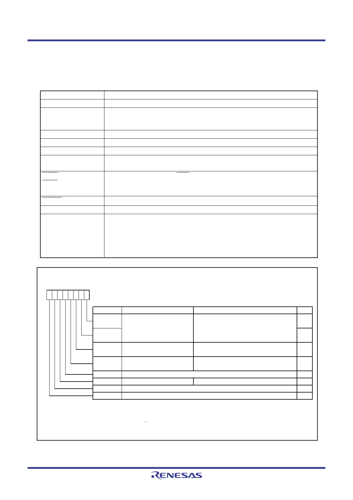
Specifications). Figure 14.4 shows the TXMR Register in Timer Mode.
Figure 14.4 TXMR Register in Timer Mode
Table 14.2 Timer Mode Specifications
Item Specification
Count sources f1, f2, f8, fRING
Count operations • Decrement
• When the timer underflows, the contents of the reload register are reloaded
and the count is continued.
Divide ratio 1/(n+1)(m+1) n: value set in PREX register, m: value set in TX register
Count start condition 1 (count starts) is written to the TXS bit in the TXMR register.
Count stop condition 0 (count stops) is written to the TXS bit in the TXMR register.
Interrupt request
generation timing
When timer X underflows [timer X interrupt].
INT10
/CNTR00,
INT11
/CNTR01
pin functions
Programmable I/O port, or INT1
interrupt input
CNTR0
pin function
Programmable I/O port
Read from timer The count value can be read out by reading registers TX and PREX.
Write to timer • When registers TX and PREX are written while the count is stopped, values are
written to both the reload register and counter.
• When registers TX and PREX are written during the count, the value is written
to each reload register of registers TX and PREX at the following count source
input, the data is transferred to the counter at the second count source input,
and the count re-starts at the third count source input.
Timer X Mode Register
Symbol Address After Reset
TXMR
008Bh 00h
Bit Symbol Bit Name Function RW
INT1
____
/CNTR0 signal
polarity sw itch bit
(1, 2)
NOTES :
1.
2.
3. Refer to
14.1.6 Notes on Timer X
for precautions regarding the TXS bit.
The IR bit in the INT1IC register may be set to 1 (requests interrupt) w hen the R0EDG bit is rew ritten.
Refer to
12.5.5 Changing Interrupt Sources
.
R0EDG RW
RW
TXOCNT RW
TXMOD2
This bit is used to select the polarity of INT1
____
interrupt in timer mode.
Set to 0 in timer mode.
TXMOD0 RW
Operating mode select bits 0, 1
b1 b0
0 0 : Timer mode or pulse period measurement
mode
TXMOD1 RW
00
b7 b6 b5 b4
00000
RW
b3 b2
0 : Rising edge
1 : Falling edge
TXS
Timer X count start flag
(3)
0 : Stops counting.
1 : Starts counting.
b1 b0
RW
TXUND RW
TXEDG Set to 0 in timer mode.
Set to 0 in timer mode.
Operating mode select bit 2 0 : Other than pulse period measurement mode
 Loading...


