R8C/1A Group, R8C/1B Group 15. Serial Interface
Rev.1.30 Dec 08, 2006 Page 152 of 315
REJ09B0252-0130
15. Serial Interface
The serial interface consists of two channels (UART0 and UART1). Each UARTi (i = 0 or 1) has an exclusive timer to
generate the transfer clock and operates independently.
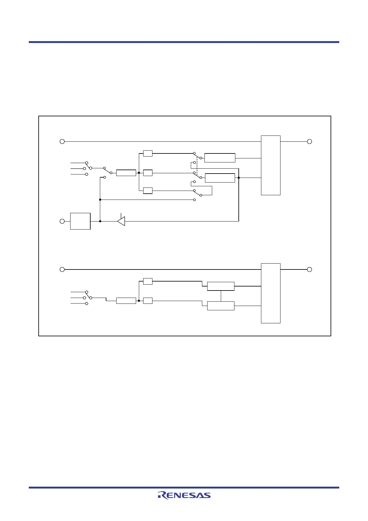
Figure 15.1 shows a UARTi (i = 0 or 1) Block Diagram. Figure 15.2 shows a UARTi Transmit/Receive Unit.
UART0 has two modes: clock synchronous serial I/O mode and clock asynchronous serial I/O mode (UART mode).
UART1 has only clock asynchronous serial I/O mode (UART mode).
Figures 15.3 to 15.6 show the Registers Associated with UARTi.
Figure 15.1 UARTi (i = 0 or 1) Block Diagram
= 01b
f8
f1
= 10b
CLK1 to CLK0 = 00b
RXD0
f32
1/16
1/16
1/2
1/(n0+1)
UART reception
UART transmission
Clock synchronous type
(when internal clock is selected)
Clock
synchronous type
Reception control
circuit
Transmission
control circuit
CKDIR = 0
CKDIR = 1
Receive
clock
Transmit
clock
Transmit/
receive
unit
U0BRG register
CKDIR = 0
Internal
External
CKDIR=1
(UART0)
TXD0
CLK
polarity
reversing
circuit
CLK0
Clock
synchronous type
Clock synchronous type
(when external clock is selected)
Clock synchronous type
(when internal clock is selected)
RXD1
1/16
1/(n1+1)
UART reception
UART transmission
Receive clock
Transmit clock
Transmit/
receive
unit
U1BRG
register
(UART1)
TXD1
= 00b
= 01b
f8
f1
= 10b
CLK1 to CLK0
f32
1/16
Internal
Reception
control circuit
Transmission
control circuit
 Loading...


