R8C/1A Group, R8C/1B Group 14. Timers
Rev.1.30 Dec 08, 2006 Page 120 of 315
REJ09B0252-0130
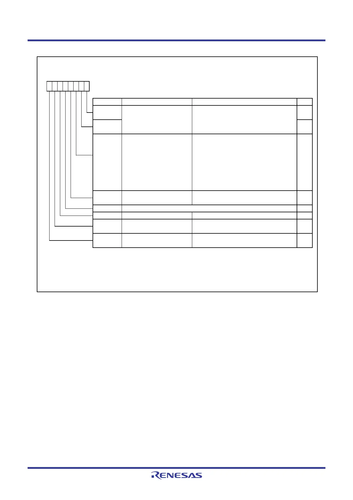
Figure 14.9 TXMR Register in Pulse Period Measurement Mode
Timer X Mode Register
Symbol Address After Reset
TXMR
008Bh 00h
Bit Symbol Bit Name Function RW
INT1
____
/CNTR0 signal
polarity sw itch bit
(1)
RW
[INT1]
_____
0 : Rising edge
1 : Falling edge
NOTES :
1.
2.
3. Refer to
14.1.6 Notes on Timer X
for precautions regarding the TXS bit.
This bit is set to 0 by w riting 0 in a program. (It remains unchanged even if w riting 1.)
RW
TXUND
(2)
RW
TXEDG
(2)
0 : Active edge not received
1 : Active edge received
Timer X underflow flag 0 : No underflow
1 : Underflow
RW
The IR bit in the INT1IC register may be set to 1 (requests interrupt) w hen the R0EDG bit is rew ritten.
Refer to
12.5.5 Changing Interrupt Sources
.
b3 b2
TXS
Timer X count start flag
(3)
b1 b0
TXMOD0
10
b7 b6 b5 b4
RW
TXOCNT RW
TXMOD2 1 : Pulse period measurement mode
Active edge judgment flag
0 : Stops counting.
1 : Starts counting.
Set to 0 in pulse w idth measurement mode.
Operating mode select bit 2
RW
Operating mode select bits 0, 1
b1 b0
0 0 : Timer mode or pulse period measurement
mode
RW
R0EDG
[CNTR0]
0 : Measures measured pulse from one
rising edge to next rising edge.
1 : Measures measured pulse from one
falling edge to next falling edge.
00
TXMOD1
 Loading...


