R8C/1A Group, R8C/1B Group 16. Clock Synchronous Serial Interface
Rev.1.30 Dec 08, 2006 Page 192 of 315
REJ09B0252-0130
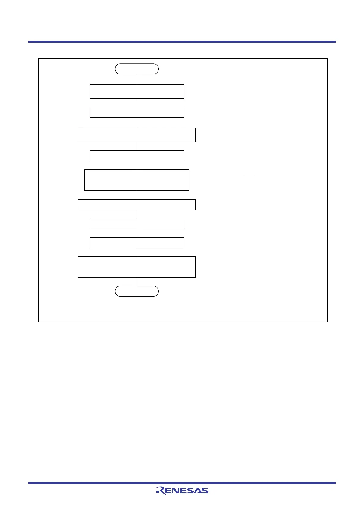
Figure 16.18 Initialization in 4-Wire Bus Communication Mode
Start
SSMR2 register SSUMS bit ← 1
SSCRH register Set bits CKS0 to CKS2
SSSR register ORER bit ← 0
(1)
SSER register RE bit ← 1 (receive)
TE bit
← 1 (transmit)
Set bits RIE, TEIE, and TIE
End
SSER register RE bit ← 0
TE bit
← 0
SSCRH register Set RSSTP bit
(2) Set the BIDE bit to 1 in bidirectional mode and
set the I/O of the SCS pin by bits CSS0 to
CSS1.
(1)
(1) The MLS bit is set to 0 for MSB-first transfer.
The clock polarity and phase are set by bits
CPHS and CPOS.
(2)
NOTE:
1. Write 0 after reading 1 to set the ORER bit to 0.
SSMR2 register SCKS bit ← 1
Set bits SOOS, CSS0 to
CSS1, and BIDE
SSCRH register Set MSS bit
SSMR register Set bits CPHS and CPOS
MLS bits
← 0
 Loading...


