R8C/1A Group, R8C/1B Group 10. Clock Generation Circuit
Rev.1.30 Dec 08, 2006 Page 70 of 315
REJ09B0252-0130
10.4.2.4 Exiting Wait Mode
The MCU exits wait mode by a hardware reset or a peripheral function interrupt. To use a hardware reset to exit
wait mode, set bits ILVL2 to ILVL0 for the peripheral function interrupts to 000b (interrupts disabled) before
executing the WAIT instruction.
The peripheral function interrupts are affected by the CM02 bit. When the CM02 bit is set to 0 (peripheral
function clock does not stop in wait mode), all peripheral function interrupts can be used to exit wait mode.
When the CM02 bit is set to 1 (peripheral function clock stops in wait mode), the peripheral functions using the
peripheral function clock stop operating and the peripheral functions operated by external signals can be used to
exit wait mode.
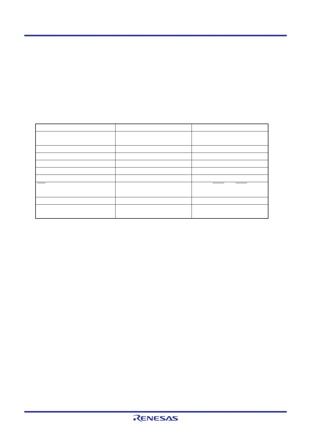
Table 10.3 lists Interrupts to Exit Wait Mode and Usage Conditions.
Table 10.3 Interrupts to Exit Wait Mode and Usage Conditions
Interrupt CM02 = 0 CM02 = 1
Serial interface interrupt Usable when operating with
internal or external clock
Usable when operating with
external clock
Key input interrupt Usable Usable
A/D conversion interrupt Usable in one-shot mode (Do not use)
Timer X interrupt Usable in all modes Usable in event counter mode
Timer Z interrupt Usable in all modes (Do not use)
Timer C interrupt Usable in all modes (Do not use)
INT
interrupt
Usable
Usable (INT0 and INT3 can be
used if there is no filter.)
Voltage monitor 2 interrupt Usable Usable
Oscillation stop detection
interrupt
Usable (Do not use)
 Loading...


