2. Engage the fan by exerting slight pressure.
3. Remove the control from the top-hat rail.
10.5 Demounting the control
10.5.1 Separating function modules from the control (if function mod-
ules were mounted)
1. Remove the left end clamp first.
2. Slide the function modules along the top-hat rail to the left until the plug
connection of the PCI
PLUS
bus is separated.
10.5.2 Removing the first Rexroth Inline terminal (if Inline terminals
were mounted)
1. Start with the first Inline terminal mounted to the right of the control.
All connectors of the terminal have to be removed.
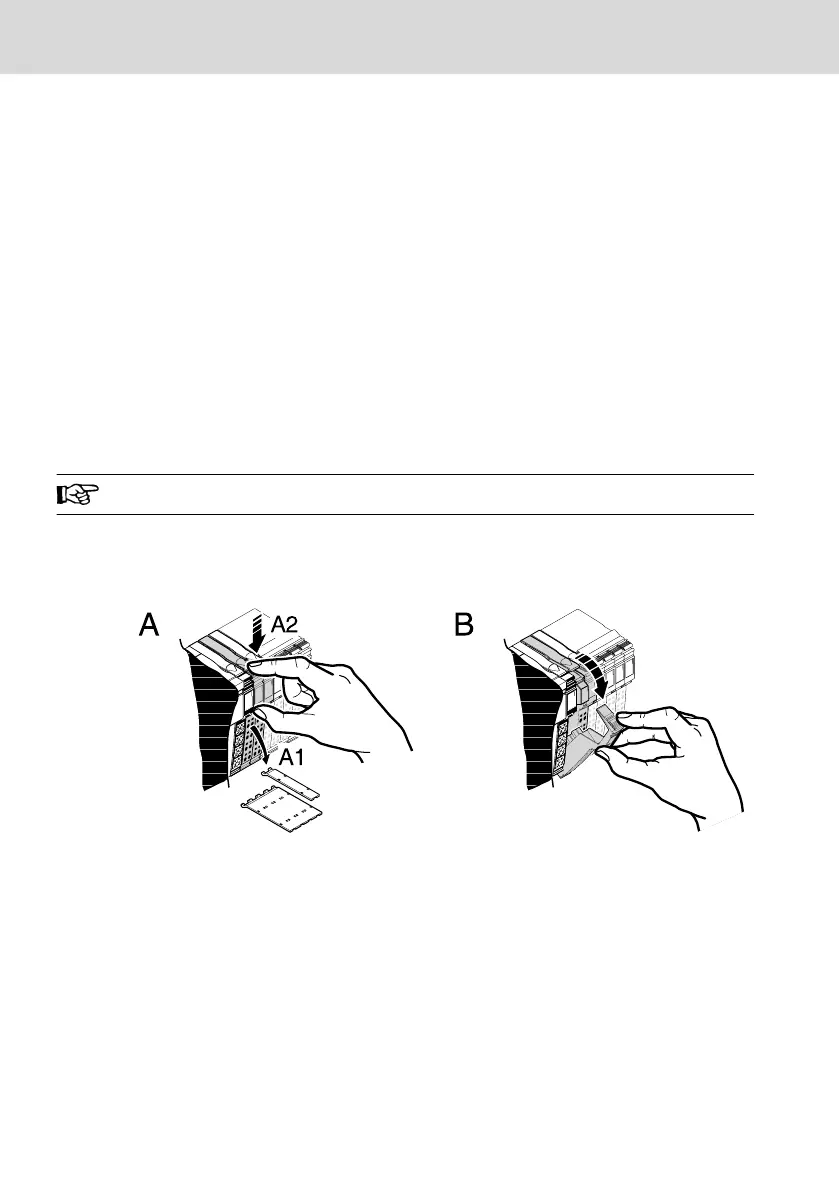
2. Remove the labeling field if present (A1 in 10-14).
3. Lever the connector of the terminal to be removed by pressing on the rear
connector shaft latching (A2 in 10-14).
Fig. 10-14: Removing the labeling field and connectors
4. Remove the connectors (B in 10-14).
5. Remove the power connector from the control.
This ensures that the tongues of the voltage jumping and the tongue and
groove joints are not damaged. Moreover, the terminal can be accessed
more easily.
6. Push the release mechanism (1 in 10-15). Then, remove the terminal per-
pendicularly to the top-hat rail (2 in 10-15).
Bosch Rexroth AG
Mounting, demounting and electric installation
L25, L45, L65, L75 and L85
26/53
DOK-CONTRL-IC*LX5*****-IT02-EN-P
 Loading...