10.7.9 Digital onboard inputs on the controls L45, L65, L75 and L85
IN 1, IN 2, IN 5, IN 6
IN 3, IN 4, IN 7, IN 8
+24 V
+24 V
Sensor
+24 V
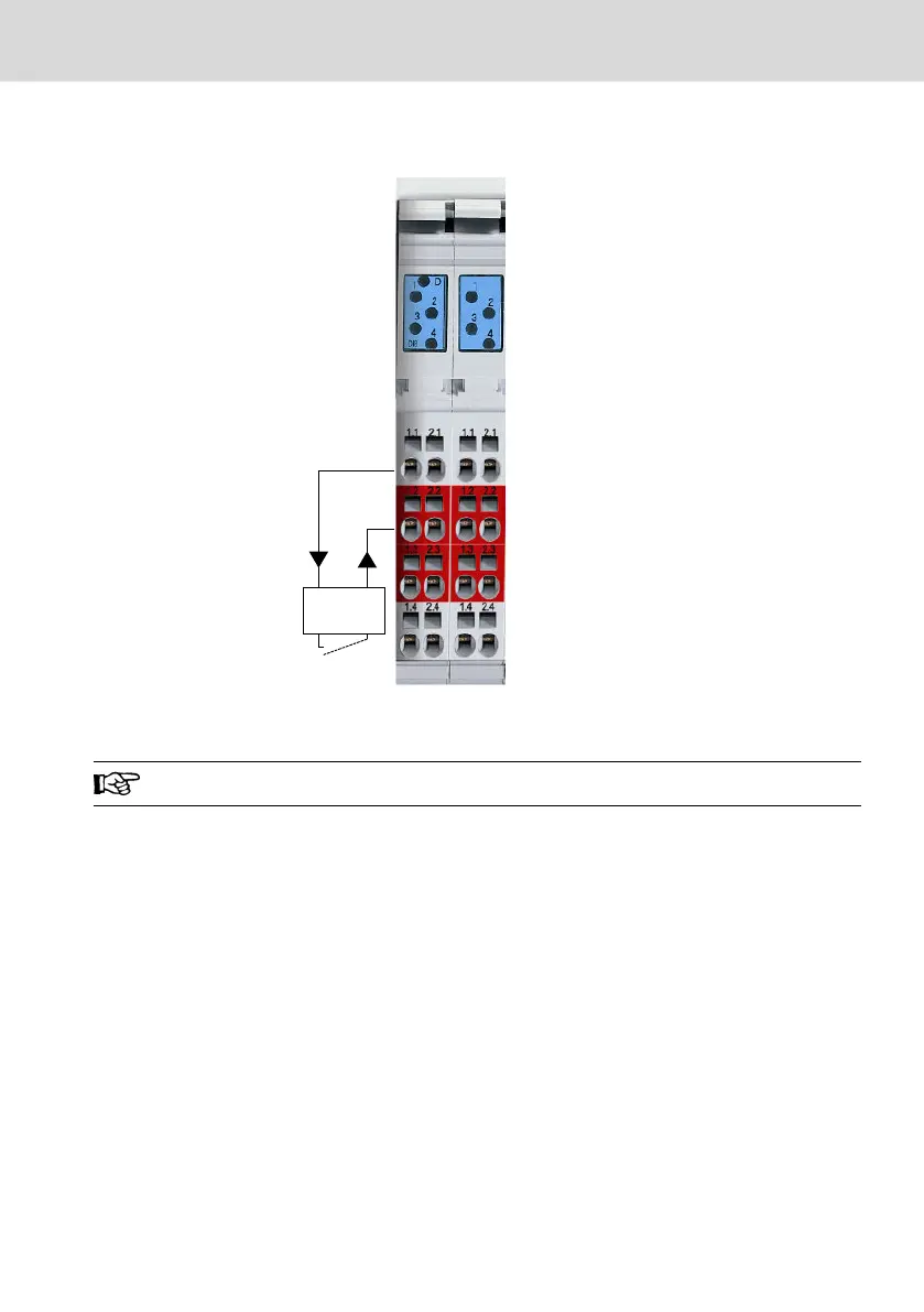
IN 1
Fig. 10-25: L45, L65, L75 and L85: Digital inputs at the connector set "R-IB IL CML S01-
PLSET"
Observe the color-coding of the plugs!
The input terminals are provided with LEDs displaying the respective state of the
inputs.
For further information, please refer to the project planning manual of the con-
trols L45/L65/L85 (R911332116).
10.7.10 Digital onboard outputs on the controls L45, L65, L75 and L85
Eight digital outputs are arranged on the slots 3 and 4 between the digital in-
puts and the power terminals.
L25, L45, L65, L75 and L85
Bosch Rexroth AG
Mounting, demounting and electric installation
DOK-CONTRL-IC*LX5*****-IT02-EN-P
39/53

 Loading...
