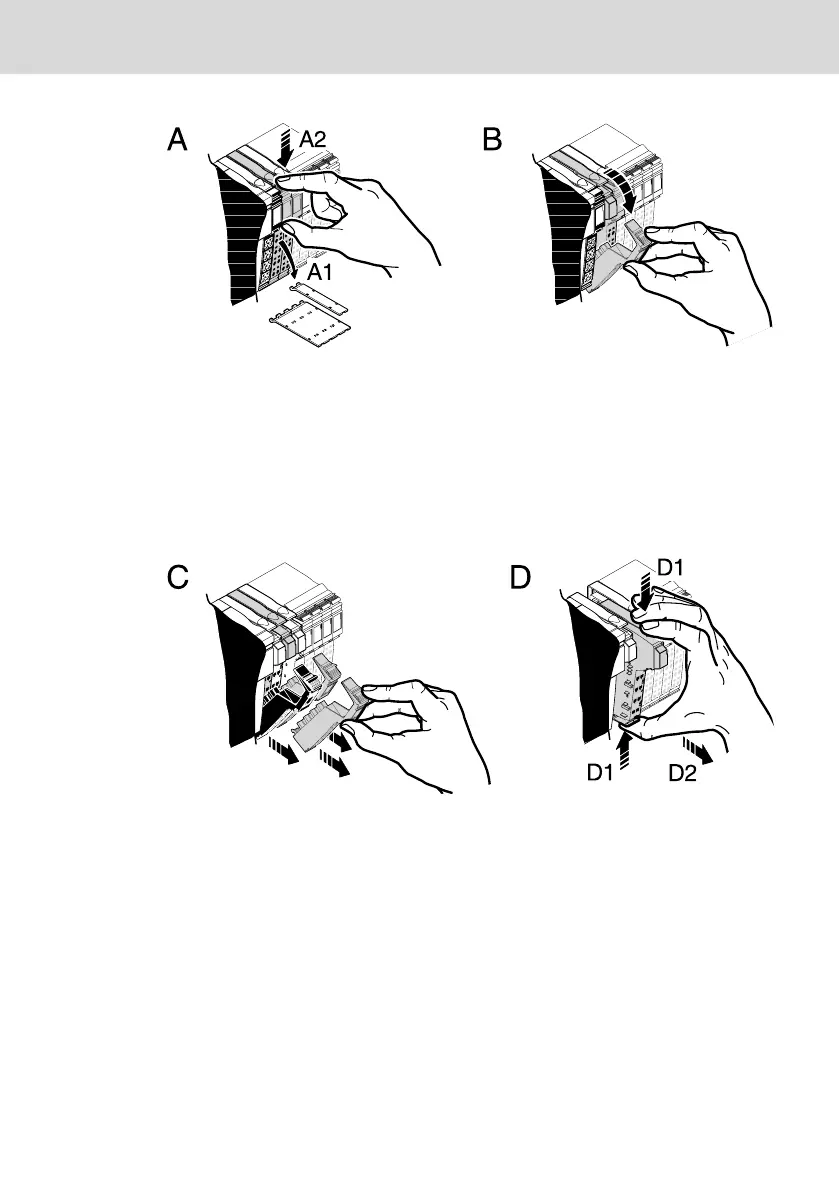
Fig. 10-18: Removing the labeling field and connectors
3. Remove the connector (B in figure 10-18).
4. Remove the adjacent connectors of the neighboring terminals (C in figure
10-19).
This ensures that the tongues of the voltage jumping and the tongue and
groove joints are not damaged. Moreover, the terminal can be accessed
more easily.
Fig. 10-19: Removing the terminal
5. Push the release mechanism (D1 in figure 10-19).
6. Remove the terminal perpendicularly to the top-hat rail (D2 in figure
10-19).
To protect the tongues of the voltage jumping and the tongue and groove
joint, the connector of the neighboring terminal to the left becomes loose if
it has not already been loosened.
10.6.2 Changing an Inline terminal
1. Remove the new terminal (see preceding section).
L25, L45, L65, L75 and L85
Bosch Rexroth AG
Mounting, demounting and electric installation
DOK-CONTRL-IC*LX5*****-IT02-EN-P
29/53
 Loading...