The grooves in the terminal are not continued in the connector. A ter-
minal can only be snapped on if there is no connector to the left. If
necessary, remove the connector.
Once the station has been set up, individual terminals can be replaced sub-
sequently by being pulled out or plugged in without any additional tools.
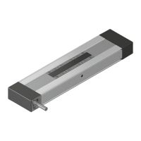
10.3.4 Mounting the shielding plate
1. The shielding plate has to form the mechanical end to the right of the con-
trol, irrespective of whether Rexroth Inline terminals have been mounted in
series.
Control failure due to missing shielding
plate
Mount the shielding plate at the right end of the control to protect the con-
trol from ESD pulses.
Dangerous contact voltages possible due
to missing shielding plate.
Mount the shielding plate at the right end of the control.
10.3.5 Mounting function modules (optional)
1. Subsequently, place the function modules on the top-hat rail to the left of
the control.
2. Slide the function modules along the top-hat rail up to the left side of the
control until a secure connection is established via the PCI
PLUS
bus.
10.3.6 Mounting the end clamp
1. To correctly connect the control on the top-hat rail, finally attach end
clamps at both sides of the Inline station.
Bosch Rexroth AG
Mounting, demounting and electric installation
L25, L45, L65, L75 and L85
24/53
DOK-CONTRL-IC*LX5*****-IT02-EN-P

 Loading...