IndraControl L85
ETH
ETH
1 2 3
Stop
Reset
Ready
X2R
X7E5
S
L
Dist.
S1
1.1
PE
1.2
1.3
1.4
2.1
2.2
2.3
2.4
PE
GND (ULS)
GND (US, UM)
UM
US
ULS
FE
Overvoltage
category I 24 V
Logic power supply unit
Separable
connections
0 V +24 V
1
2
(1)
Load power supply unit
0 V +24 V
PE
E.g..
terminal strip UKS6-FSI/6
circuit breaker TCP10 A
from Phoenix-Contact
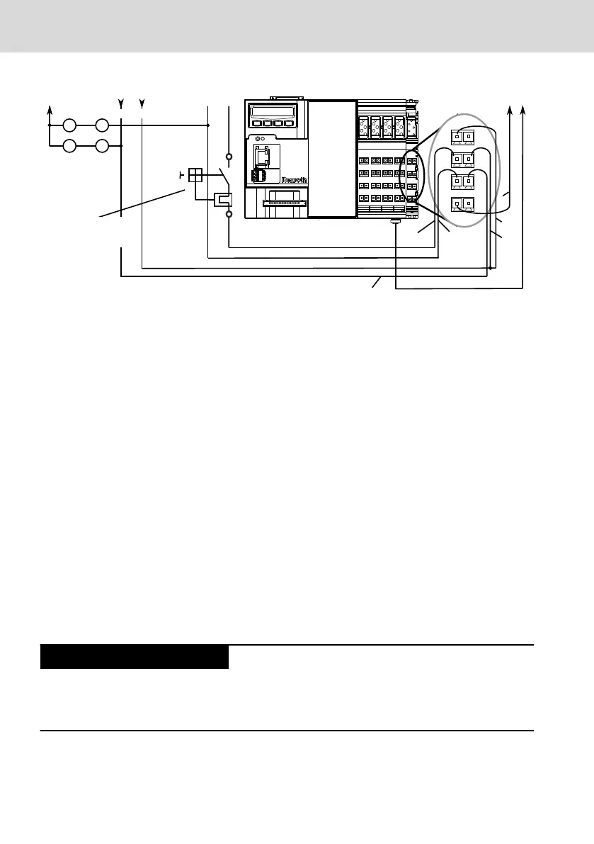
1 Polarity reversal can result in device destruction (fire hazard) if no additional external
protection is provided. The reason for the risk of destruction is the simultaneous ground-
ing of the GND (U
LS
) in the device and of the GND (U
LS
) load (PELV) at the power supply
unit. Install the external fuse.
Fig. 10-22: Reference conductor connected to protective conductor
Dimensioning the voltage supply
Observe the maximum currents when dimensioning the voltage supply. A voltage
between 20.4 V and 28.8 V has to be applied directly at the device.
The voltage must also be observed in the following cases:
● In case of fluctuations in the line voltage caused by different network loads
for example
● In case of different load states, such as short-circuit, normal load, lamp load
or no load
The maximum conductor cross-section for the voltage supply is 1.5 mm
2
.
10.7.5 Grounding
General information
Control failure due to insufficient grounding
Ensure grounding. An optimum grounding
is required to keep away possible interferences from the control and from the
Rexroth Inline terminals and to discharge them to the ground.
Bosch Rexroth AG
Mounting, demounting and electric installation
L25, L45, L65, L75 and L85
34/53
DOK-CONTRL-IC*LX5*****-IT02-EN-P

 Loading...
