IndraControl L85
ETH
ETH
1 2 3
Stop
Reset
Ready
X2R
X7E5
S
L
Dist.
S1
1.1
PE
1.2
1.3
1.4
2.1
2.2
2.3
2.4
PE
GND (ULS)
GND (US, UM)
UM
US
GND (US, UM)
ULSFE
FE
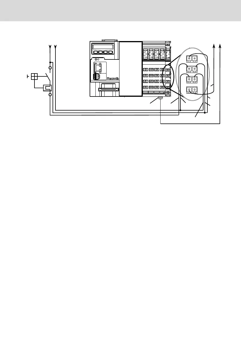
Overvoltage
category I 24 V
E.g.
terminal strip UKS6-FSI/6
circuit breaker TCP10 A
from PHOENIX CONTACT
Load and logic supply unit
+ 24 V 0 V
1
2
(1)
1 Polarity reversal can result in device destruction (fire hazard) if no additional external
protection is provided. The reason for the risk of destruction is the simultaneous ground-
ing of the GND (U
LS
) in the device and of the GND (U
LS
) load (PELV) at the power supply
unit. Install the external fuse.
Fig. 10-21: Setup without electrical isolation
Reference conductor connected to the protective conductor and set up with
electrical isolation
Provide electrical isolation between the logic of the central processing unit and
the I/O interfaces of the peripheral devices acc. to DIN EN 60204-1. The voltage
U
LS
(24 V logic voltage) is electrically isolated from the voltages U
S
(24 V seg-
ment voltage) and U
M
(24 V main voltage) at the control.
If the reference conductor GND U
LS
is connected to the protective conductor
system, this connection has to be arranged at a central place (e. g. at the load
power supply unit). Hence, the supply current circuit is a PELV circuit.
L25, L45, L65, L75 and L85
Bosch Rexroth AG
Mounting, demounting and electric installation
DOK-CONTRL-IC*LX5*****-IT02-EN-P
33/53

 Loading...
