Home
REXROTH
Control Unit
IndraControl L25
REXROTH IndraControl L25 User Manual
5
of 1
of 1 rating
60 pages
Give review
Manual
Specs
To Next Page
To Next Page
To Previous Page
To Previous Page
Loading...
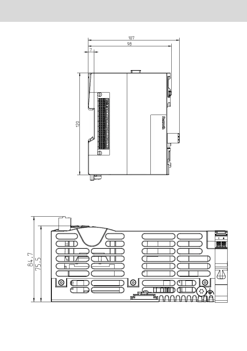
Fig. 10-4:
L45, L65 and 75 (without fan), left view (in mm), the cut-out f
or the top-hat rail is
arranged centrally
10.2.2
Housing dimensions L25
Fig. 10-5:
L25, bott
om view (in mm)
L25, L45, L65, L75 and L85
Bosch Re
xroth A
G
Mounting, demounting and electric installation
DOK-CONTRL
-IC*LX5*****-IT02-EN-P
19/
53
24
26
Table of Contents
Default Chapter
3
Table of Contents
3
1 About this Documentation
7
2 Product Identification and Scope of Delivery
9
Product Identification
9
Scope of Delivery
9
3 Use of the Safety Instructions
10
Structure of the Safety Instructions
10
Explaining Signal Words and Safety Alert Symbol
10
Symbols Used
11
Signal Graphic Explanation on the Device
11
4 Intended Use
12
5 Spare Parts, Accessories and Wear Parts
12
Connector Set for the Control
12
Connector Set for the Control L25
12
Fan for the Controls L45, L65, L75 and L85
13
Battery for the Controls L45, L65, L75 and L85
13
Display Set
13
Cap for Compact Flash Slot
13
Power Supply Unit
13
Wear Parts
13
6 Ambient Conditions
14
7 Technical Data
16
General Technical Data
16
Voltage Supply and Current and Power Consumption
17
8 Standards
18
Standards Used
18
CE Marking
18
Declaration of Conformity
18
UL/CSA Certified
19
9 Interfaces
20
Dok-Contrl -IC*Lx5*****-It02-En-P I
20
Interface View
20
Overview
21
10 Mounting, Demounting and Electric Installation
22
Installation Notes
22
Housing Dimensions
23
Housing Dimensions of the L45, L65, L75 and L85
23
Housing Dimensions L25
25
Housing Dimensions of the Fan
27
Mounting the Control
27
General Information
27
Mounting the Control on the Top-Hat Rail
28
Mounting Rexroth Inline Terminals (Optional) in Series
28
Mounting the Shielding Plate
30
Mounting Function Modules (Optional)
30
Mounting the End Clamp
30
Mounting the Fan (if Necessary)
31
Demounting the Control
32
Separating Function Modules from the Control (if Function Modules Were Mounted)
32
Removing the First Rexroth Inline Terminal (if Inline Terminals Were Mounted)
32
Removing Control from Top-Hat Rail
33
Demounting and Changing the Inline Terminals
34
Removing an Inline Terminal
34
Changing an Inline Terminal
35
Electric Installation
36
General Information
36
External Power Supply Unit
36
Voltage Supply for the Control
36
Voltage Supply
38
Grounding
40
Shielding
42
Connecting Lines (for Digital Onboard Inputs, Outputs and Voltage Supply) to Tension Spring Connection Points
42
Information on the Control Use above 2,700 M above Sea Level
43
Digital Onboard Inputs on the Controls L45, L65, L75 and L85
45
Digital Onboard Outputs on the Controls L45, L65, L75 and L85
45
Further Interfaces
47
11 Commissioning
47
General Information
47
Commissioning Steps
47
12 Device Description
49
General Information
49
13 Error Causes and Troubleshooting
50
14 Maintenance
50
General Information
50
Regular Maintenance Tasks
50
Display (LCD)
51
Lithium Battery
51
15 Ordering Information
53
Type Code Lx5
53
Accessories and Spare Parts
53
16 Disposal
54
General Information
54
Return
54
Packaging
54
Batteries and Accumulators
54
17 Service and Support
54
Index
57
5
Based on 1 rating
Ask a question
Give review
Questions and Answers:
Need help?
Do you have a question about the REXROTH IndraControl L25 and is the answer not in the manual?
Ask a question
REXROTH IndraControl L25 Specifications
General
Brand
REXROTH
Model
IndraControl L25
Category
Control Unit
Language
English
Related product manuals
REXROTH IndraControl L45
60 pages
REXROTH IndraControl L65
60 pages
REXROTH IndraControl L75
60 pages
REXROTH IndraControl L40 Series
130 pages
REXROTH CS351
55 pages
REXROTH CKR Series
48 pages