2. First snap on the terminal required to set up the station perpendicularly to
the top-hat rail (A in figure 10-10).
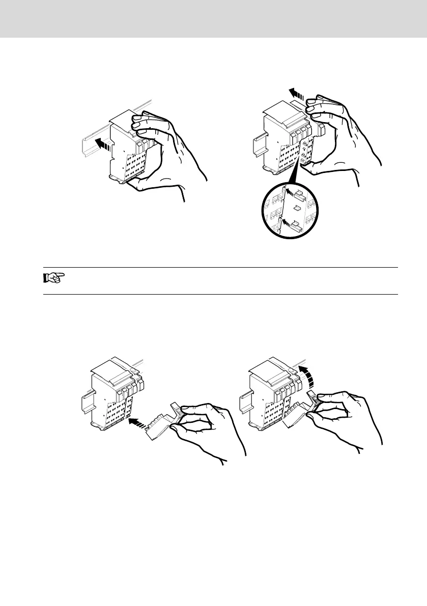
Fig. 10-10: Snapping on the terminal on the top-hat rail
Ensure that all tongues and grooves of neighboring terminals are in-
terlocked (B in figure 10-10).
The tongue and groove joint connects neighboring modules with each oth-
er. After snapping on the terminal on the top-hat rail, continue as follows:
3. Attach the connectors onto the respective terminal.
Fig. 10-11: Fastening the connectors
4. First fit the front connector shaft latching into the front release mechanism
(C in figure 10-11).
5. Press the connector towards the terminal until it clicks into the rear release
mechanism (D in figure 10-11).
L25, L45, L65, L75 and L85
Bosch Rexroth AG
Mounting, demounting and electric installation
DOK-CONTRL-IC*LX5*****-IT02-EN-P
23/53

 Loading...
