OUT 1, OUT 2, OUT 5, OUT 6
OUT 3, OUT 4, OUT 7, OUT 8
GND
GND
OUT1
GND
Actuator
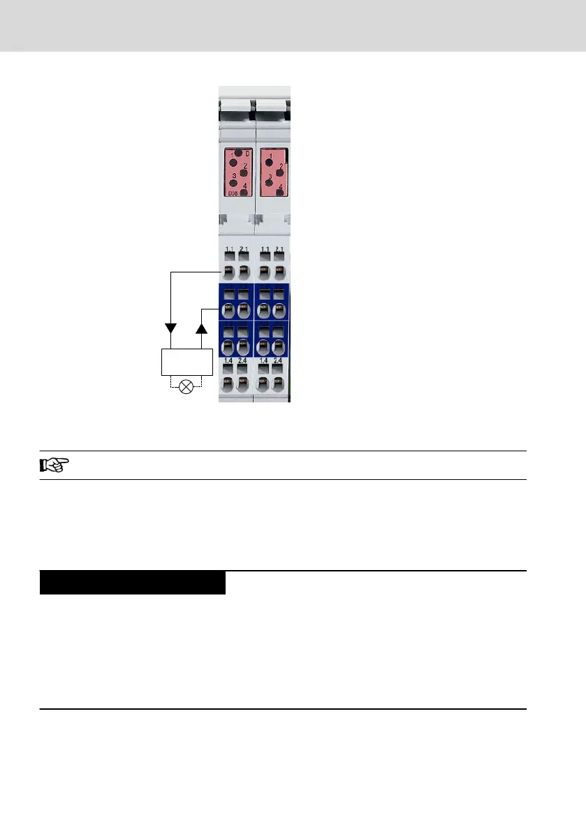
Fig. 10-26: L45, L65, L75 and L85: Digital inputs at the connector set "R-IB IL CML S01-
PLSET"
Observe the color-coding of the plugs!
The output terminals are provided with LEDs displaying the respective state of
the outputs.
For further information, please refer to the project planning manual of the con-
trols L45/L65/L85.
Destruction of the component group due to im-
proper connection
● Avoid polarity reversal with simultaneous short circuit of the output lines
● Avoid polarity reversal with simultaneous connection of externally polarized
suppressor diodes
● Avoid applying an external voltage greater than the segment voltage U
S
at the
digital output
Bosch Rexroth AG
Mounting, demounting and electric installation
L25, L45, L65, L75 and L85
40/53
DOK-CONTRL-IC*LX5*****-IT02-EN-P

 Loading...
