For the control L25: To connect the supply voltage, only the power
connector (R-IB IL SCN-PWR IN-PWR) may be used for the control
L25.
For the controls L45, L65, L75 and L85: To connect the supply volt-
age, only the power connector (R-IB IL SCN-PWR IN-PWR) may be
used.
The connector R-IB IL SCN-PWR IN-CP, which is available for other
power terminals, is not allowed for the control!
Power connectors for the controls
UM
US
UL
FS
FN
UM
US
UL
FS
FN
PWR
UM
US
UL
FS
FN
PWR
1
2
3
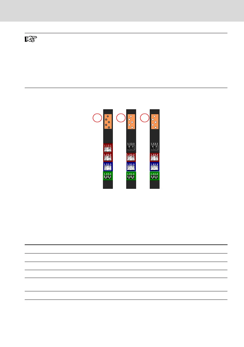
① Power connector for the controls L45,
L65, L75 and L85 from the connector
set "R-IB IL CML S01-PLSET"
② Power connector for the controls L45,
L65, L75 and L85 from the connector
set "R-IB IL CML S04-PLSET"
③ Power connector for the control L25
from the connector set "R-IB IL SCN-
PWR IN-PWR"
Fig. 10-20: Power connector for the control
Connector
contact
Signal (control L25) Signal (control L45, L65, L75, L85)
1.1 +24 V DC segment voltage (U
S
) +24 V DC segment voltage (U
S
)
1.2 +24 V DC supply voltage (U
LS
) +24 V DC supply voltage (U
LS
)
1.3 GND (U
LS
) (ground supply voltage) GND (U
LS
) (ground supply voltage)
1.4 and 2.4 FE (functional earth) FE (functional earth)
2.1 +24 V DC main voltage (U
M
) +24 V DC uninterruptable power supply
(UPS) is currently not supported
2.2 +24 V DC main voltage (U
M
) +24 V DC main voltage (U
M
)
2.3 GND (U
S
, U
M
) (ground main and seg-
ment voltage)
GND (U
S
, U
M
) (ground main and segment volt-
age)
Tab. 10-1: Pin assignment of the power terminal of the control
L25, L45, L65, L75 and L85 Bosch Rexroth AG
Mounting, demounting and electric installation
DOK-CONTRL-IC*LX5*****-IT02-EN-P
31/53

 Loading...
