RE 30126-01-B/08.07 | Manual Hydraulics | Bosch Rexroth AG 11/76
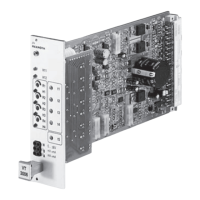
Overview of the 4WRE 6 and 4WRE 10 – Valve control 2
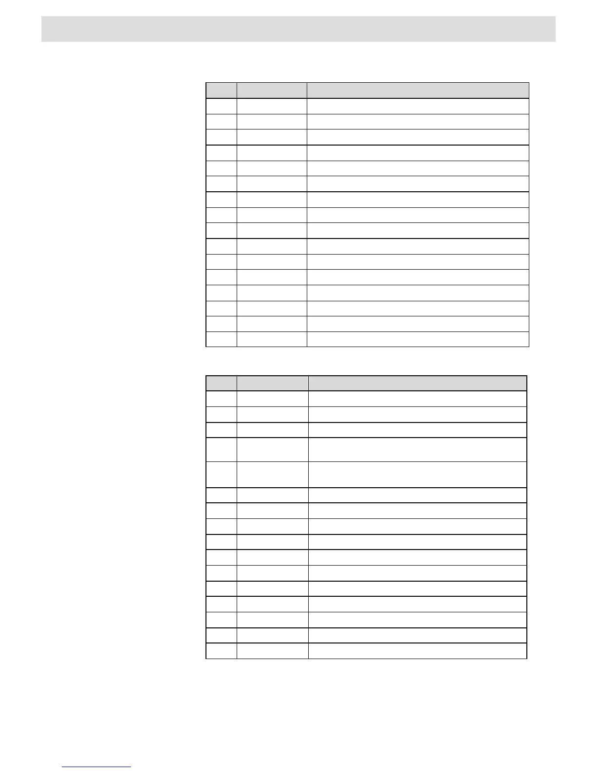
Pin Description VT-VRPD-2-2X
2 MA+ Solenoid A+
4 MA – Solenoid A–
6 MB+ Solenoid B+
8 MB – Solenoid B–
10 Shield Shield
12 L1O– LVDT Valve Power –
14 L1I– LVDT Valve actual value –
16 L1I+ LVDT Valve actual value +
18 L1O+ LVDT Valve Power +
20 System ground System ground
22 DO 3 Following error > configured value
24 DO 4 Digital Output, programmable
26 DO 5 Digital Output, programmable
28 DO 6 Digital Output, programmable
30 UB Supply voltage
32 LO Common
Tab. 3 Connector configuration, row z
Pin Description VT-VRPD-2-2X
2 DO 7 n.c.
4 SSI Clk+ n.c.
6 SSI Clk- n.c.
8
SSI Data+ /
INC Ua1
n.c.
10
SSI Data -/
INC /Ua1
n.c.
12 Ua2 n.c.
14 /Ua2 n.c.
16 Ua0 n.c.
18 /Ua0 n.c.
20 L2O- n.c.
22 L2I- n.c.
24 L2I+ n.c.
26 L2O+ n.c.
28 GND_CAN n.c.
30 CANL n.c.
32 CANH n.c.
Tab. 4 Connector configuration, row f
Row z