RE 30126-01-B/08.07 | Manual Hydraulics | Bosch Rexroth AG 14/76
Overview of the 4WRE 6 and 4WRE 10 – Valve control 2
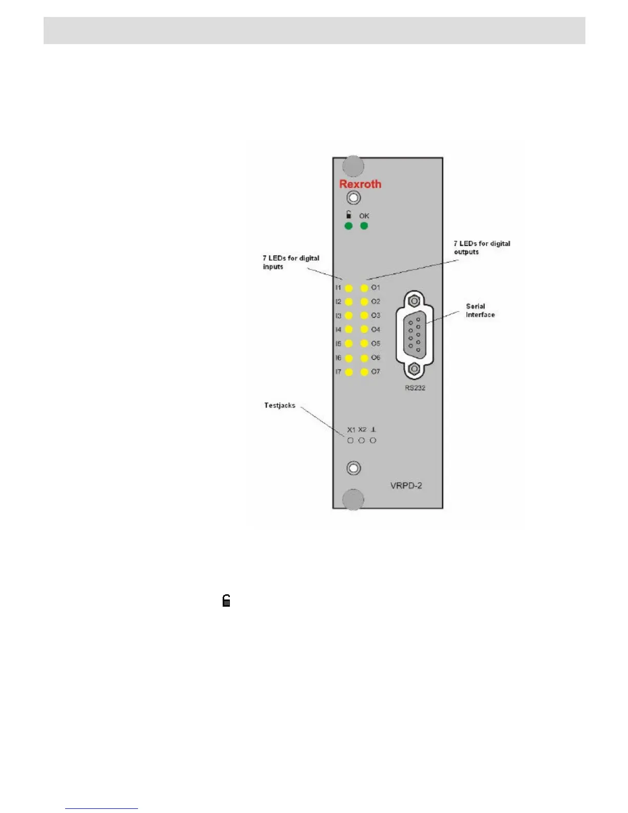
2.3 Controller faceplate elements
Fig. 4 Faceplate elements
The LED indicates the status of the controller card.
OK “Ready”
“Enable“ (d18) active
The controller cards software is configured using the serial port. The following graphic
shows the pin configuration for the D-SUB female on the front panel.
Status-LED
Serial port