RE 30126-01-B/08.07 | Manual Hydraulics | Bosch Rexroth AG 10/76
Overview of the 4WRE 6 and 4WRE 10 – Valve control 2
Connector pin assignments
Pin Description
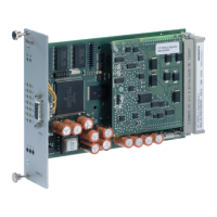
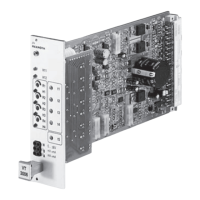
VT-VRPD-2-2X
2 DI 1 Command call-up: Binary 1
4 DI 2 Command call-up: Binary 2
6 DI 3 Command call-up: Binary 4
8 DI 4 Command call-up: Binary 8
10 DI 5 n.c.
12 DI 6 DI 1 – 4 valid
14 DI 7 n.c.
16 DI 8 n.c.
18 DI9 Enable
20 DO 1 Solenoid A active
22 OK Ready for operation
24 Data + Local CAN Bus In-/Output
26 DO 2 Solenoid B active
28 Data – Local CAN Bus In-/Output
30 AO 1 Valve command value
32 AO 2 n.c.
Tab. 1 Connector configuration, row d
Pin Description VT-VRPD-2-2X
2 AI3+ n.c.
4 AI3- n.c.
6 AI2+ Ramp+ (current or voltage input)
8 AI2- Ramp+ (current or voltage input)
10 AI1+ n.c.
12 AI1- n.c.
14 AI4+ Command value (as voltage input)
16 AI4- Command value (as voltage input)
18 AI5+ Ramp- (current or voltage input)
20 AI5- Ramp- (current or voltage input)
22 AI6+ Command value (as current input)
24 AI6- Command value (as current input)
26 AO3 Solenoid current
28 AGND Analog GND
30 REF- Reference voltage -10V
32 REF+ Reference voltage +10V
Tab. 2 Connector configuration, row b
Row d