RE 30126-01-B/08.07 | Manual Hydraulics | Bosch Rexroth AG 15/76
Overview of the 4WRE 6 and 4WRE 10 – Valve control 2
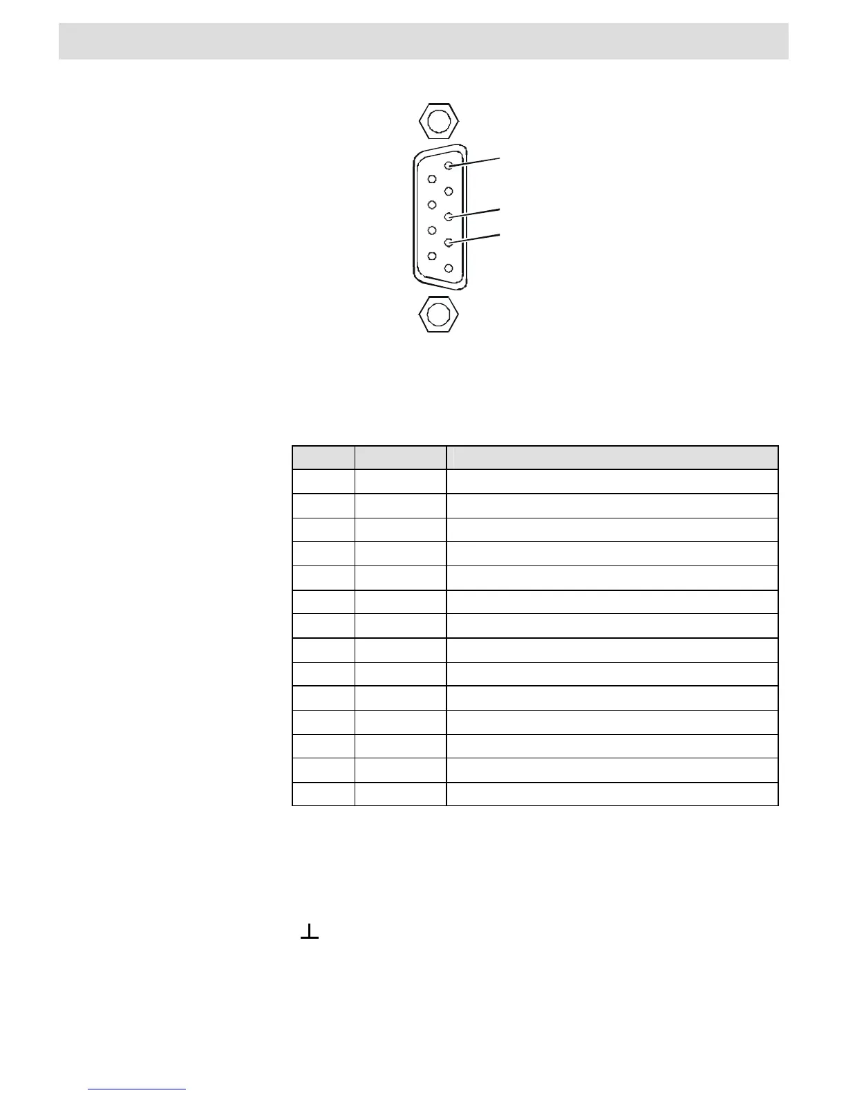
GND
5
Fig. 5 Terminal assignments for the D-SUB socket
When an input or output is active the corresponding LED is illuminated.
LED Description VT-VRPD-1-1X
I1 DI 1 Binary Command-Setpoint 1
I2 DI 2 Binary Command-Setpoint 2
I3 DI 3 Binary Command-Setpoint 4
I4 DI 4 Binary Command-Setpoint 8
I5 DI 5 n. c.
I6 DI 6 Command-Setpoint 1-4 valid
I7 - n. c.
O1 DO 1 Solenoid A active
O2 DO 2 Solenoid B active
O3 DO 3 Following error > configured value
O4 DO 4 Digital Output, programmable
O5 DO 5 Digital Output, programmable
O6 DO 6 Digital Output, programmable
O7 - n. c.
Tab. 5 LEDs on front panel
The test jacks can be used to access variable control signals.
X1 Test jack 1 (Output A03)
X2 Test jack 2
Test jack GND