13
GA--A 202
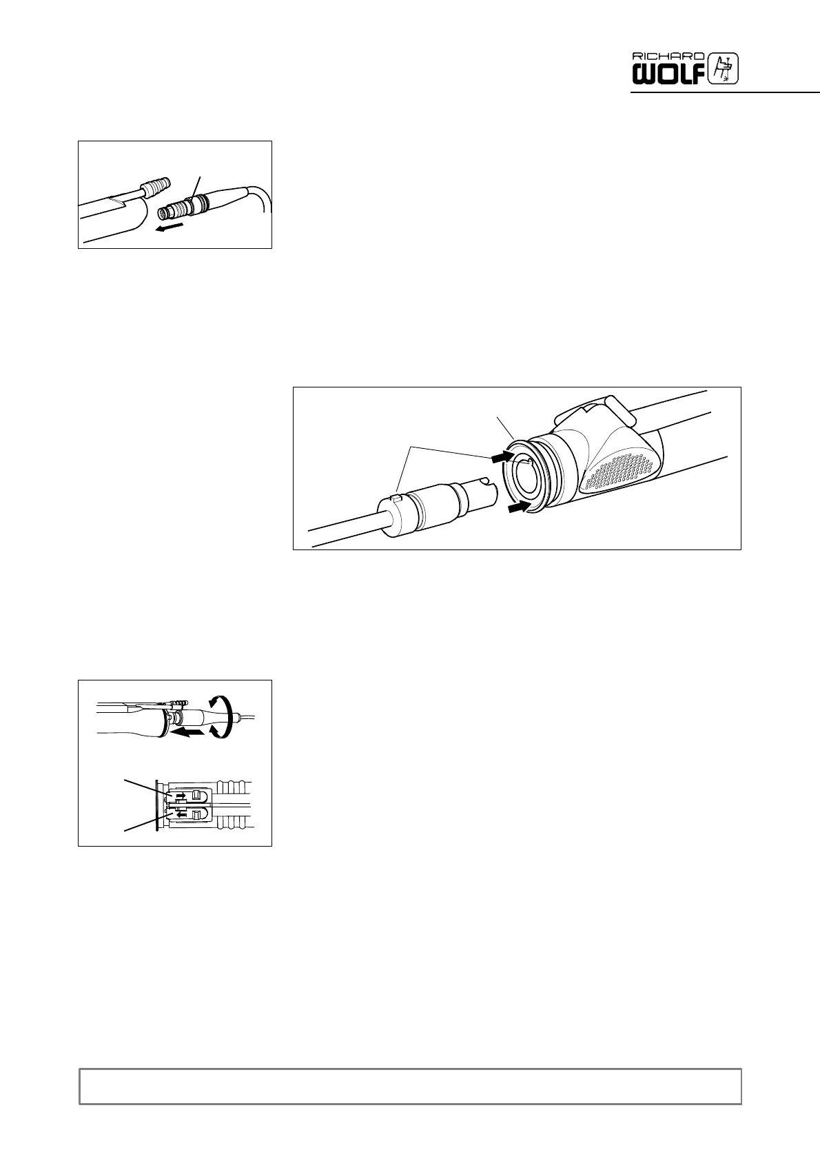
3.2 Preparation of POWER STICK M4
Z Connecting the cable to POWER STICK M4.
' Align connector (the red marking (C) must be positioned exactly be-
low the suction connector) and push home.
Z Connect suction tube between suction pump and suction connector on
POWER STICK M4. Set suction valve to “ O FF”.
Z Inserting t he rotary blades.
' Retract ring (14.8) on clamping chuck.
' Insertrotarybladeinsuchawaythatthecamisalignedwithgroove
(14.10) on the clamping chuck.
' Let go of ring, the rotary blade is locked in place.
Z ConnectthecableofPOWERSTICKM4tothePOWERCONTROL
unit.
14.10
14.8
.
IMPORTANT!
The inner and outer blades are supplied in matched pairs. Do not mix
with other blades.
3.3 Preparation of POWER STICK M3 (8563.111 / .311)
Z Connecting the cable to POWER STICK M3:
' Turn the plug with the rubber sleeve under slight pressure until it en-
gages in the socket connector. Then push both the plug and the pro-
tection sleeve home (for this the plug must be in home position).
Z Connecting the suction tube between the suction pump and the suction
connector of the motorized handle.
' Set the suction control valve (13.5) to ”closed”.
Z In the case of motorized handle 8563.311 also connect the irrigation
connector.
' Set irrigation control valve (13.6) to ”closed”.
.
NOTE!
Theirrigationpressurecanbeadjustedbyvaryingtheheightdifference
(hydrostatic pressure) between the working height and the height of the
irrigation fluid container or suction pump.
Z Inserting t he rotary blades.
' Retract ring (13.1.1) of clamping chuck.
' Insert rotary blades in such a way that cam (13.12) is aligned with
groove (13.11) on clamping chuck (13.1).
' Let go of ring, the rotary blade is locked in place.
C
13.5
13.6