39
GA--A 202
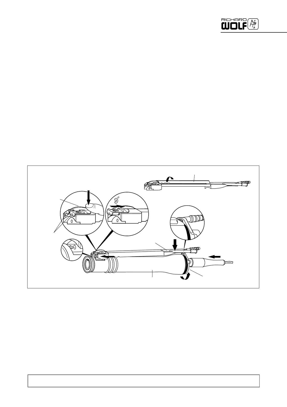
7.4.3 Assembly
After cleaning, all accessory parts must be assembled:
Z Place cover (13.10) onto suction/irrigation system (13.8).
' Install cover in a rotary motion in counter-clockwise direction and
then push down (the recesses must be on the side of the valves).
Z Lubricate the suction and irrigation valve pistons spearingly with endo
scope grease.
Z Install the suction/irrigation control valves.
' Push down lever (13.14) on the side of cover (A) as far as it will go
and push home the suction and irrigation valve plungers (13.5/13.6)
until the pin of the lever engages in the groove of the suction and
irrigation control valves.
Z Install the suction/irrigation system (13.8).
Z Insert drive unit in handle sleeve (13.7) and lock the twist-lock in the
hint portion of the locking mechanism of drive unit (13.9.1) (by turning
clockwise).
' Ensure that the pin of the suction and irrigation system engages in
the groove in the hint portion of the locking mechanism of drive unit
(13.9.1).
13.7
13.9.1
13.10
13.5/13.6
13.8
13.14
A
7.4.4 Function check
Z Check POWER STICK M3 and the suction and irrigation valve
plungers for proper functioning and possible damage after each clean
ing cycle.
Z Return a damaged POWER STICK to the factory for repair,
'
do not attempt to do any repairs yourself!