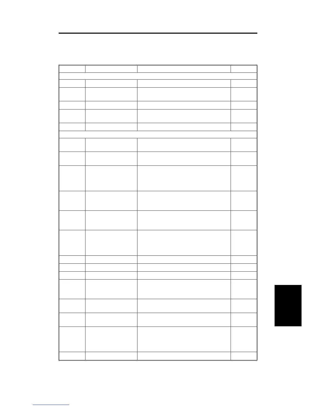
3. ELECTRICAL COMPONENT DESCRIPTION
Refer to the electrical component layout on the reverse side of the
point-to-point large size diagram for symbols and index numbers.
Symbol Name Function Index No.
Motors
M1
Friction Belt Drives the friction belt.
2
M2
Feed-in Drives the feed-in system (pick-up, feed,
pull-out rollers)
3
M3
Belt Drive Drives the transport belt.
5
M4
Feed-out Drives the feed-out and the inverter
system.
10
Sensors
S1
Feed-in Cover Open Detects whether or not the feed-in cover is
open.
1
S2
DF Position Informs the CPU whether the DJF is in the
up or down position.
7
S3
APS Start Informs the CPU when the DJF is being
closed so that the original size sensors in
the main body can check the original size
(in platen mode).
8
S4
Feed-out Checks for original misfeeds and sets
original stop timing when in auto-reverse
mode.
11
S5
Pulse Count Counts the pulses generated by the pulse
generator disc to determine the original
length.
12
S6
Registration-2 Detects the leading edge of the original to
turn off the feed-in clutch and to change
the feed-in motor speed. Also detects the
original length.
13
S7
Original Width-1 Detects the original width.
14
S8
Original Width-2 Detects the original width.
15
S9
Original Width-3 Detects the original width.
16
S10
Registration-1 Detects the original length and original
jam by detecting the trailing edge of the
original.
17
S11
Original Set Detects if originals have been placed on
the feed table.
18
S12
Original Feed Detects if the originals have reached the
feed roller or not.
19
S13
Friction Belt Turn Counts the pulses generated by the pulse
generator disk to monitor the friction belt
motor.
20
Dual Job Feeder
DF62 (A610)
SM 7-5 A172/A199