Do you have a question about the Ricoh Aficio MP171 and is the answer not in the manual?
Guidelines to prevent physical harm during machine operation and maintenance.
Precautions related to toner, developer, and ozone gas exposure for user health.
Rules for servicing the machine by trained personnel and handling NVRAM batteries.
Procedures for safely handling toner, including inhalation, skin contact, and spills.
Guidelines for the safe disposal of toner bottles, used toner, and replaced parts.
Explains symbols, abbreviations used in the manual, and lists registered trademarks.
Lists trademarks of various software and companies mentioned in the manual.
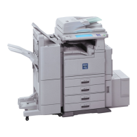
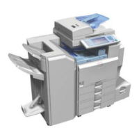
Provides a general overview of the machine's components and layout.
Illustrates the main components of the machine with numerical labels.
Diagrams showing the different paths paper takes through the machine.
Illustrates the drive system components and their arrangement within the machine.
Details machine codes, external options, and consumable part numbers.
Lists general specifications, supported paper sizes, software, and optional equipment.
Specifies environmental conditions, illumination, ventilation, and altitude for machine installation.
Details the necessary clearance around the machine for proper operation and ventilation.
Provides the physical width, depth, and height of the machine with and without options.
Outlines electrical requirements, including voltage, frequency, and current consumption.
Covers accessory checks, customer instructions, and basic installation steps.
Provides safety precautions and procedures for safely moving the machine.
Instructions for changing administrator passwords and configuring SSL/TLS for security.
Steps for configuring the machine for the @Remote service, including check points and execution.
Refers to appendices for detailed preventive maintenance schedules and items.
Defines standards for image quality, including assured image area, magnification, and linearity.
Specifies standards for paper handling, including margin position, skew, and curling after fusing.
Important safety notes regarding power switches, residual charge, and handling components.
Procedures for performing a normal and forced shutdown of the machine.
Instructions for performing a forced shutdown, cautioning against its general use.
Step-by-step instructions for removing various exterior covers of the machine.
Detailed steps for detaching and removing the front cover of the machine.
Instructions for removing the left cover, noting the location of tabs.
Instructions for removing the right cover, noting the location of tabs.
Steps for removing the rear and lower rear covers.
Instructions for removing the upper cover, including screw and connector removal.
Guidance on accessing or replacing the operation panel components.
Information on accessing and maintaining the LED head and unit.
Steps for replacing or cleaning the LED unit and its components.
Procedure to re-engage disengaged spring hooks for the LED unit holder.
Instructions for removing and replacing the PCDU (Photo Conductor Drum Unit).
Steps for removing and replacing the toner cartridge.
Procedures related to the image transfer unit and roller.
Instructions for removing and replacing the image transfer roller.
Covers components within the drive unit, such as motors and clutches.
Steps for accessing and replacing the main motor.
Procedure for replacing the toner supply clutch.
Steps for replacing the registration clutch.
Instructions for replacing the paper feed clutch.
Procedures for accessing and working with the gear unit.
Steps for replacing the by-pass feed clutch.
Instructions for replacing the relay clutch.
Steps for replacing the by-pass bottom plate clutch.
Procedures for replacing the duplex clutch.
Instructions for replacing the junction gate solenoid.
General cautions and procedures related to the fusing unit.
Steps for removing and replacing the fusing unit.
Instructions for separating the fusing unit into upper and lower parts.
Procedures for replacing the fusing pressure roller and cleaning roller.
Steps for replacing the fusing lamp and hot roller.
Instructions for accessing and replacing the thermostat.
Procedures for replacing the thermistor, including notes on reassembly.
Steps for removing and replacing the hot roller stripper.
General procedures related to the paper feed system.
Instructions for removing the paper feed tray.
Steps for detaching and replacing the paper feed roller.
Instructions for removing the friction pad.
Procedures for removing and replacing the paper end sensor.
Steps for removing and replacing the by-pass feed unit.
Instructions for removing and replacing the by-pass feed roller.
Procedures for removing and replacing the by-pass friction pad.
Steps for removing and replacing the by-pass paper end sensor.
Instructions for removing and replacing the by-pass bottom plate HP sensor.
Procedures for removing and replacing the paper size detection switch.
General procedures for paper transport components.
Steps for removing and replacing the exit/switchback sensor.
Instructions for removing and replacing the duplex entrance sensor.
Procedures for removing the exit/switchback roller and duplex exit gear.
Steps for removing and replacing the driven registration roller.
Procedures for removing and replacing the drive registration roller.
Instructions for removing and replacing the registration sensor.
Overview of electrical components and their replacement procedures.
Steps for removing and replacing the controller box.
Procedures for removing and replacing the Power Supply Unit.
Instructions for replacing the controller board.
Steps for replacing the BCU (Base Control Unit) and EEPROM.
Procedure for replacing the EEPROM chip on the BCU board.
Instructions for accessing and replacing the toner end sensor.
Procedures for replacing the High Voltage Power Supply unit.
Steps for replacing the HVPS unit along with its bracket.
Instructions for replacing the fusing fan.
Procedures for replacing the PCDU cooling fan.
Steps for replacing the PSU cooling fan.
Instructions for replacing the DC switch.
Procedures for replacing the front door interlock switch.
Steps for replacing the rear door interlock switch.
Instructions for replacing the temperature and humidity sensor.
Procedures for replacing the rear cover switch.
Overview of the Service Program Mode, including cautions and accessing SP mode.
Refers to appendices for detailed Service Program (SP) tables.
Guidelines for service representatives on accessing and securing the SP mode.
Instructions on how to access the Service Program (SP) mode, even when the control panel is locked.
Procedure for exiting the Service Program (SP) mode and making settings effective.
Describes the different types of SP modes available: System SP and Printer SP.
Comprehensive guide on updating the machine's firmware, including requirements and procedures.
General information about firmware updates, supported OS, and precautions.
Lists the supported Windows operating systems for firmware updates.
Important steps to ensure a successful firmware update, such as power options and connection checks.
Lists necessary items for firmware updates, including cables and software tools.
Step-by-step instructions for performing the firmware update process.
Information on handling firmware update errors and using the recovery mode.
Procedures for obtaining and analyzing machine operational status logs.
Introduction to obtaining debug logs from the machine.
Specifies the types of log entries that can be obtained for machine status.
Indicates that log entries are output in text format.
Lists the requirements for obtaining log entries from a PC.
Details the necessary PC software and OS compatibility for log retrieval.
Instructions for installing the driver for the dbgmon utility.
Steps for obtaining debug logs using a USB connection.
Steps for obtaining debug logs using a TCP/IP connection.
Explains the machine's self-diagnostic process upon power-on and SC code display.
Describes the initial self-diagnostic test performed when the machine is powered on.
Provides a summary of service call levels, definitions, and reset procedures for SC codes.
Categorizes service calls by level (A, B, C, D) and outlines their definitions and reset methods.
Details the operator actions and machine behavior when a Level D SC code occurs.
Lists error codes related to LED optics, including causes and solutions.
Details error codes for image processing issues, including causes and solutions.
Lists error codes related to image processing, covering causes and solutions.
Explains error codes related to paper feed and fusing, with causes and solutions.
Details the main motor error, its causes, and suggested solutions.
Explains the fusing fan error, its causes, and recommended solutions.
Describes errors related to the fusing thermistor wire and their remedies.
Covers software-related high-temperature errors in the fusing unit.
Addresses hardware issues causing high-temperature detection in the fusing unit.
Explains zero-crossing errors due to adhered relay contacts and their solutions.
Details software-related high-temperature errors for the end thermistor.
Covers software issues causing high-temperature detection in the end fusing thermistor.
Lists error codes related to device communication failures, including causes and solutions.
Details engine communication errors and troubleshooting steps.
Explains errors related to incorrect remote service IDs and their causes.
Lists various EEPROM communication errors and their potential causes.
Describes engine start-up errors and troubleshooting steps.
Explains errors when the toner cartridge device ID is not identified.
Details errors when the PCDU device ID is not identified.
Covers errors where the PRREQ signal is not asserted, including causes and solutions.
Lists error codes related to peripheral devices.
Explains errors when the number of paper tray units exceeds the maximum limit.
Lists error codes related to the controller unit.
Details energy save I/O subsystem errors and their causes.
Explains watchdog timer errors and potential solutions.
Covers self-diagnostic errors related to the engine I/F ASIC.
Lists error codes that do not fit into other categories.
Explains errors related to the electronic total counter being out of range.
Details printer application errors that stop machine operation.
Covers software performance errors and troubleshooting steps.
Describes software continuity errors where operation can continue with recovery.
Explains undefined SC errors not covered by other codes.
Details errors related to CPM setting mismatches, often due to BCU or NVRAM issues.
Covers errors related to application function selection or abnormal termination.
Explains errors that occur when applications fail to start or render properly.
Information on detecting and identifying paper jams within the machine.
Describes the four-line display messages indicating paper jam locations.
Diagrams showing the location of various sensors used for jam detection.
Explains jam codes (causes) and position codes (locations) for paper jams.
Lists jam codes and position codes specific to the main machine.
Lists jam codes and position codes for optional paper banks.
Instructions for printing a test sheet to check and adjust print settings.
Guidance on adjusting image position, including blank margin width and print area.
Procedures for adjusting registration, including print area checks and side-to-side registration.
Checks that the image adjustment meets the product specification.
Specifies reference values for leading edge, trailing edge, left, and right adjustments.
Steps for performing registration adjustments using test sheets and SP modes.
Identifies image problems that occur at regular intervals due to component circumference.
Solutions for vertical banding issues, potentially improved by drum rotation function.
Methods to resolve black spots on print images, possibly using fusing roller cleaning.
Provides a flowchart to diagnose and correct paper skew issues.
Advice for handling paper curling issues with recycled or thin paper.
General information about energy saving features and modes to reduce power consumption.
Explains different energy saver modes and the impact of timer settings on energy savings.
Details how to set the duration before the printer enters Sleep mode.
| Resolution | 600 x 600 dpi |
|---|---|
| Maximum Paper Size | A3 |
| Paper Capacity | 250 sheets |
| Max Paper Capacity | 1, 350 sheets |
| Printing Technology | Laser |
| Power Source | 220 - 240V, 50/60Hz |
| Copy Speed | 17 ppm |
| Multiple Copy | Up to 99 |
| Zoom Range | 50% to 200% |