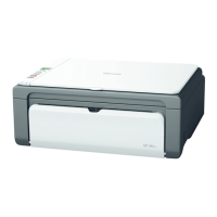
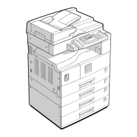
ELECTRICAL COMPONENT LAYOUT (B384)
B384V102.WMF
7
1
8
9
6
5
4
2
3
14
13
12
11
10
15
16
18
19
17
20
Symbol Name Index No. P-to-P
Motors
M1 Paper Feed 20 E12
M2 Lower Lift 18 E13
M3 Upper Lift 3 E13
Sensors
S1 Lower Paper Height 2 10 E8
S2 Lower Paper Height 1 11 E9
S3 Upper Paper Height 2 4 E9
S4 Upper Paper Height 1 5 E9
S5 Vertical Transport 12 E10
S6 Lower Paper End 14 E10
S7 Upper Paper End 13 E11
S8 Lower Lift 19 E13
S9 Upper Lift 2 E13
Switches
SW1 Upper Paper Size 16 E9
SW2 Lower Paper Size 15 E10
SW3 Tray Cover 8 E11
Magnetic Clutches
MC1 Upper Paper Feed 6 E11
MC2 Relay 7 E11
MC3 Lower Paper Feed 9 E12
PCBs
PCB1 Tray Main 1 D9-13
Others
H1 Optional Tray Heater 17 E14
 Loading...


