20 February, 2001 SCANNER SECTION
3-17
Replacement
Adjustment
3.4.10 ADJUSTMENT OF 1ST AND 2ND SCANNER ALIGNMENT
For how to use this procedure, see the previous section, ‘Adjustment of 2nd
Scanner Position’.
1. Remove the A(R)DF or platen cover.
2. Remove the operation panel (☛ 3.3.5).
3. Remove the top rear cover (☛ 3.3.7).
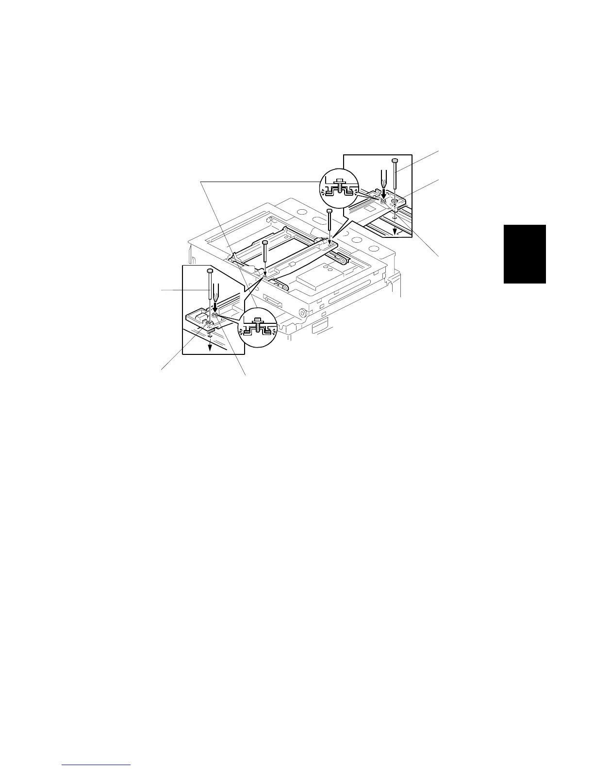
4. Loosen the 2 screws [A] holding the 1st and 2nd scanner belts in place.
5. Slide the 1st and 2nd scanners so that all three of the following are aligned on
both sides:
• The second hole from the right on each 2nd scanner arm
• The position guide holes on the upper and lower mainframe rims
• The 1st scanner position guide hole [B]
6. Insert the positioning tools [C] into both sets of holes.
7. Make sure that both the 1st and 2nd scanner belts are properly set in place on
both sides [D].
8. Re-tighten the screws loosened in step 1 [A] to clamp the scanner belts in
place, then remove the positioning tools.
B039R007.WMF
[B]
[A]
[D]
[C]
[A]
[B]
[C]
 Loading...


