6
Caution: At the last projector, the DMX cable has to be terminated with a 120 Ω resistor. Solder the resistance
into a 3 pin XLR-connector and plug it in the DMX-output of the last projector.
3.4.Connecting PC
The 9-pin female connector on the rear panel of the unit is reserved for connection the controller to the PC via RS-
232 interface.
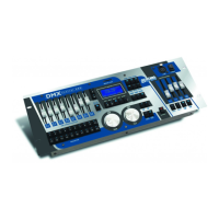
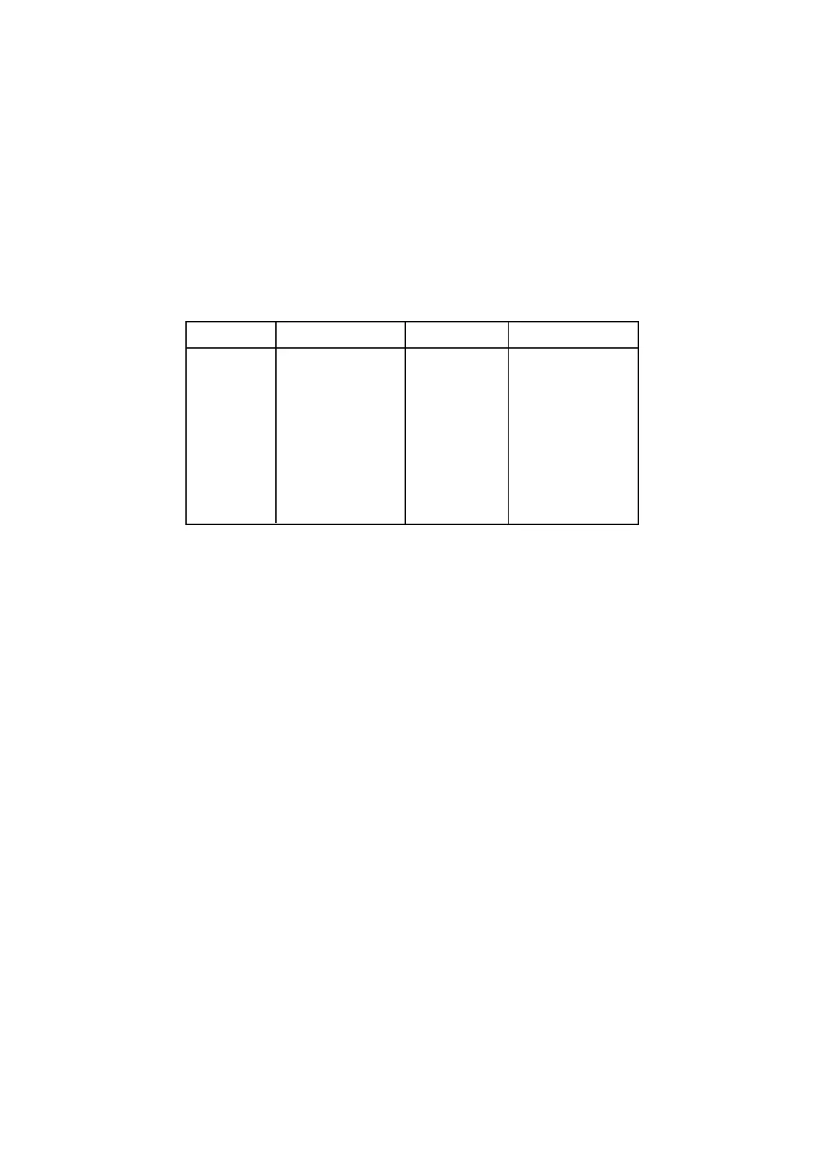
3.5.Projector addressing
The DMX CONTROL 480 assigns the DMX-starting addresses every 24 steps. You have to address every projector
to the respective starting address. Otherwise, the channel assignment will not be correct. All projectors with the
same starting address will work synchronically.
Projector Starting address Projector Starting adress
Projector 1 1 Projector 11 241
Projector 2 25 Projector 12 265
Projector 3 49 Projector 13 289
Projector 4 73 Projector 14 313
Projector 5 97 Projector 15 337
Projector 6 121 Projector 16 361
Projector 7 145 Projector 17 385
Projector 8 169 Projector 18 409
Projector 9 193 Projector 19 433
Projector 10 217 Projector 20 457
 Loading...